|
|
|
|
Faceset1@pipe
|
pipe.SLDPRT
|
|
|
Faceset2@pipe
|
pipe.SLDPRT
|
|
|
Faceset1@adaptor
|
adaptor.SLDPRT
|
|
|
Faceset2@adaptor
|
adaptor.SLDPRT
|
|
|
adaptor.SLDPRT
|
||
|
Faceset1@housing
|
housing.SLDPRT
|
|
|
Faceset2@housing
|
housing.SLDPRT
|
|
|
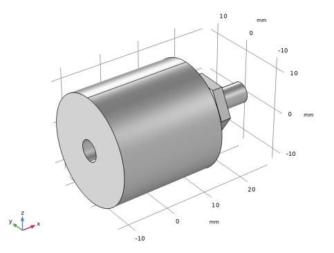
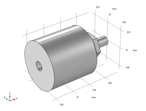
pipe_fitting.SLDPRT
|
|
1
|
In SOLIDWORKS open the file pipe_fitting_cad/pipe_fitting.SLDASM located in the model’s Application Library folder.
|
|
3
|
|
1
|
|
2
|
Click
|
|
1
|
|
2
|
|
3
|
|
1
|
|
2
|
|
3
|
Click Synchronize.
|
|
4
|
Click to expand the Object Selections section. Click to expand the Boundary Selections section. The selections listed in these sections are defined on the geometry in the SOLIDWORKS assembly. For more details see Notes About the COMSOL Implementation.
 |
|
1
|
|
2
|
|
3
|
|
1
|
|
2
|
|
1
|
|
2
|
|
3
|
Select the Selections from 3D checkbox.
|
|
4
|
Click
|
|
1
|
|
2
|
|
3
|
|
1
|
|
2
|
|
3
|
|
4
|
Clear the Create pairs checkbox.
|
|
1
|
|
2
|
|
3
|
|
1
|
|
2
|
Go to the Add Material window.
|
|
3
|
|
4
|
Right-click and choose Add to Component 2 (comp2).
|
|
5
|
|
1
|
|
2
|
Go to the Add Physics window.
|
|
3
|
|
4
|
Click the Add to Component 2 button in the window toolbar.
|
|
5
|
|
1
|
|
2
|
|
3
|
|
4
|
Locate the Destination Boundaries section. From the Selection list, choose Faceset2@adaptor (Cross Section 1).
|
|
1
|
|
2
|
|
3
|
|
4
|
Locate the Destination Boundaries section. From the Selection list, choose Faceset1@adaptor (Cross Section 1).
|
|
1
|
|
2
|
|
3
|
|
4
|
Locate the Destination Boundaries section. From the Selection list, choose Faceset1@pipe (Cross Section 1).
|
|
1
|
|
2
|
|
3
|
Click
|
|
4
|
In the Add dialog, in the Pairs list, choose Contact Pair 1 (p1), Contact Pair 2 (p2), and Contact Pair 3 (p3).
|
|
5
|
Click OK.
|
|
6
|
|
7
|
From the list, choose Augmented Lagrangian.
|
|
1
|
|
2
|
|
3
|
|
1
|
|
1
|
|
2
|
|
3
|
Click
|
|
4
|
Browse to the model’s Application Libraries folder and double-click the file pipe_fitting_parameters.txt.
|
|
1
|
|
2
|
|
3
|
|
4
|
|
1
|
|
2
|
In the Show More Options dialog, in the tree, select the checkbox for the node Physics > Equation Contributions.
|
|
3
|
Click OK.
|
|
1
|
|
2
|
|
4
|
|
5
|
|
6
|
Click OK.
|
|
7
|
|
8
|
Click
|
|
9
|
|
10
|
Click OK.
|
|
1
|
|
2
|
|
3
|
Click
|
|
4
|
|
5
|
|
1
|
|
3
|
|
4
|
From the list, choose Diagonal.
|
|
5
|
|
1
|
|
2
|
|
3
|
From the list, choose User-controlled mesh.
|
|
1
|
|
2
|
|
3
|
|
4
|
|
5
|
|
6
|
Locate the Element Size Parameters section.
|
|
7
|
|
8
|
Click
|
|
1
|
|
2
|
Go to the Add Study window.
|
|
3
|
|
4
|
Right-click and choose Add Study.
|
|
5
|
|
1
|
|
3
|
|
4
|
Click
|
|
1
|
|
2
|
|
3
|
In the Model Builder window, expand the Study 1 > Solver Configurations > Solution 1 (sol1) > Stationary Solver 1 > Segregated 1 node, then click Solid Mechanics.
|
|
4
|
|
5
|
|
6
|
|
1
|
|
2
|
|
3
|
|
1
|
|
2
|
|
3
|
Select the Show maximum and minimum values checkbox.
|