|
|
|
|
1
|
In AutoCAD open the file busbar_surface.dwg located in the model’s Application Library folder.
|
|
1
|
|
2
|
|
3
|
Click Add.
|
|
4
|
Click
|
|
5
|
|
6
|
Click
|
|
1
|
|
2
|
|
3
|
|
1
|
|
2
|
|
3
|
Click Synchronize.
|
|
4
|
Click to expand the Parameters in CAD Package section. The table contains the two parameters, width and d5, which are part of the AutoCAD model. In AutoCAD, the Parameter Selection button on the COMSOL Multiphysics tab allows you to select and view parameters for synchronization. These parameters are retrieved, and appear in the CAD name column of the table. The corresponding entries in the COMSOL name column, LL_width and LL_d5, are global parameters in the COMSOL model. These are automatically generated during synchronization, and are assigned the values of the linked AutoCAD dimensions. The parameter values are displayed in the COMSOL value column.
|
|
5
|
Click to expand the Object Selections section. The selections displayed here are automatically generated based on the assigned materials in the AutoCAD file.
|
|
1
|
|
2
|
Click in the Graphics window and then press Ctrl+A to select all objects.
|
|
3
|
|
1
|
|
2
|
|
3
|
|
4
|
Click
|
|
5
|
|
6
|
Click OK.
|
|
7
|
|
8
|
|
1
|
|
2
|
|
3
|
|
4
|
Click
|
|
5
|
|
6
|
Click OK.
|
|
7
|
|
8
|
|
1
|
|
2
|
|
3
|
|
4
|
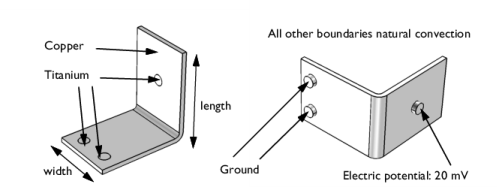
On the object fin, select Boundaries 8 and 15 only. These are the bolt faces labeled with Ground in Figure 2.
|
|
1
|
|
2
|
In the Settings window for Explicit Selection, type Electric potential boundary in the Label text field.
|
|
3
|
|
4
|
On the object fin, select Boundary 31 only. This is the bolt face labeled with Electric potential in Figure 2.
|
|
1
|
|
2
|
|
3
|
|
4
|
|
5
|
|
6
|
Click OK.
|
|
7
|
|
8
|
|
9
|
In the Add dialog, in the Selections to subtract list, choose Grounded boundaries and Electric potential boundary.
|
|
10
|
Click OK.
|
|
1
|
|
2
|
|
3
|
Click
|
|
4
|
Browse to the model’s Application Libraries folder and double-click the file busbar_parameters.txt.
|
|
1
|
|
2
|
Go to the Add Material window.
|
|
3
|
|
4
|
Click the Add to Component button in the window toolbar.
|
|
1
|
|
2
|
|
1
|
Go to the Add Material window.
|
|
2
|
|
3
|
Click the Add to Component button in the window toolbar.
|
|
4
|
|
1
|
|
2
|
|
1
|
|
2
|
|
3
|
|
1
|
|
2
|
|
3
|
|
4
|
|
1
|
|
2
|
|
3
|
|
4
|
|
5
|
|
1
|
|
2
|
|
3
|
Click
|
|
4
|
|
5
|
Click
|
|
6
|
|
7
|
|
8
|
|
9
|
Click Replace.
|
|
10
|
|
11
|
|
12
|
Click
|
|
14
|
|
15
|
Click
|
|
16
|
|
17
|
|
18
|
|
19
|
Click Replace.
|
|
20
|
|
21
|
|
22
|
|
23
|
|
1
|
|
2
|
|
3
|
|
1
|
|
2
|
|
3
|
|
4
|
|
5
|
|
6
|
|
7
|
|
8
|
|
9
|
|
10
|
|
1
|
|
2
|
|
3
|
|
4
|
Click
|
|
1
|
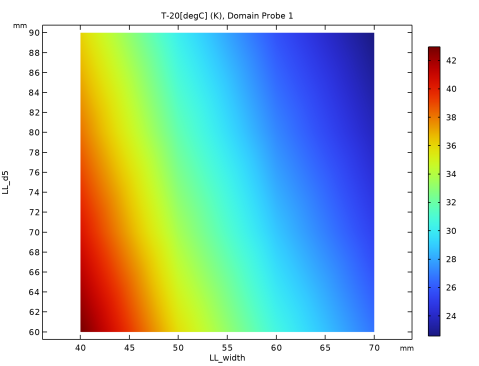
Go to the Probe Table 1 window.
|
|
2
|
Click the Table Surface button in the window toolbar.
|
|
1
|
|
2
|
|
3
|
|
4
|
|
5
|
|
6
|
|
7
|
|
1
|
|
2
|
|
3
|
Select the Manual data range checkbox.
|
|
4
|
|
5
|
|
1
|
|
2
|
|
3
|
|
4
|
|
1
|
|
2
|
|
3
|
|
4
|
|
5
|
|
6
|
|
7
|
|
8
|
|
1
|
|
2
|
|
3
|
|
4
|
|
5
|
|
6
|
|
7
|
|
8
|
|
9
|