PDF

Minimizing the Drying Time of a Wood Particle
Introduction
This model is inspired by the Superheated Steam Drying of a Wood Particle model. In this example, optimization is applied to find the optimal temperature control that minimizes the drying time.
Model Definition
A Control Function feature is used to allow a time-varying inlet temperature. The average temperature is constrained to be below 150°C, while the final moisture content should be below 4%.
Results and Discussion
Figure 1 shows the optimized control function.
Figure 1: The optimal temperature control is nontrivial in the sense that it has a minimum.
Figure 2 shows the moisture content as a function of time. It can be concluded that the time-varying temperature saves around 10% of the processing time. The assumptions made during the optimization matter for the intermediate times, but the effect is marginal for the final time..
Figure 2: The moisture content for three constant temperatures together with the time-varying temperature with and without accounting for temperature variations in the flow.
Application Library path: Heat_Transfer_Module/Phase_Change/superheated_steam_drying_optimization
Modeling Instructions
This example starts from an existing model from the Heat Transfer Module Application Library.
Application Libraries
1
From the File menu, choose Application Libraries.
2
In the Application Libraries window, select Heat Transfer Module > Phase Change > superheated_steam_drying in the tree.
3
Global Definitions
Parameters 1
1
In the Model Builder window, under Global Definitions click Parameters 1.
2
In the Settings window for Parameters, locate the Parameters section.
3
Definitions (comp1)
Control Function 1 (cfunc1)
1
In the Model Builder window, expand the Component 1 (comp1) node.
2
Right-click Component 1 (comp1) > Definitions and choose Control Variables > Control Function.
3
In the Settings window for Control Function, locate the Input section.
4
From the Extrapolation list, choose Linear, because the tolerance of the bisection associated with the stop condition might cause the argument to be marginally outside the bounds.
5
Locate the Output section. In the fmin text field, type Tmin.
6
In the fmax text field, type Tmax.
7
In the c0 text field, type 0.5*(Tmax+Tmin).
8
Locate the Control Variable Discretization section. From the Control type list, choose Piecewise Bernstein polynomial.
9
Locate the Units section. Click  Select Input Quantity.
10
In the Physical Quantity dialog, select General > Dimensionless (1) in the tree.
11
12
In the Settings window for Control Function, locate the Units section.
13
Click  Select Output Quantity.
14
In the Physical Quantity dialog, select General > Temperature (K) in the tree.
15
Shared Properties
Ambient Properties 1 (ampr1)
1
In the Model Builder window, expand the Component 1 (comp1) > Definitions > Shared Properties node, then click Ambient Properties 1 (ampr1).
2
In the Settings window for Ambient Properties, locate the Ambient Conditions section.
3
In the Tamb text field, type cfunc1(t/tmax).
4
In the ϕamb text field, type mt.pA/mt.fpsat(cfunc1(t/tmax)).
Using cfunc1(t/tmax) instead of cfunc1(t) ensures that the entire range of the Control Function is utilized.
Laminar Flow (spf)
1
In the Model Builder window, under Component 1 (comp1) click Laminar Flow (spf).
2
In the Settings window for Laminar Flow, locate the Physical Model section.
3
From the Compressibility list, choose Incompressible flow.
Heat Transfer in Moist Air (ht)
1
In the Model Builder window, under Component 1 (comp1) click Heat Transfer in Moist Air (ht).
2
In the Settings window for Heat Transfer in Moist Air, locate the Physical Model section.
3
In the Tref text field, type T_avg.
Study 1: Initial Control
1
In the Model Builder window, click Study 1.
2
In the Settings window for Study, type Study 1: Initial Control in the Label text field.
Lets neglect the effect of the temperatures variations on the flow by using a stationary flow in the analysis for the heat transfer and moisture transport.
Add Study
1
In the Home toolbar, click  Windows and choose Add Study.
2
Go to the Add Study window.
3
Find the Studies subsection. In the Select Study tree, select General Studies > Stationary.
4
Click the Add Study button in the window toolbar.
5
In the Select Study tree, select Empty Study.
6
Click the Add Study button in the window toolbar twice.
7
In the Home toolbar, click  Add Study to close the Add Study window.
Study 2
Step 1: Stationary
1
In the Settings window for Stationary, locate the Physics and Variables Selection section.
2
In the Solve for column of the table, under Component 1 (comp1), clear the checkboxes for Heat Transfer in Moist Air (ht) and Moisture Transport in Free and Porous Media (mt).
3
In the Solve for column of the table, under Component 1 (comp1) > Multiphysics, clear the checkboxes for Moisture Flow 1 (mf1), Heat and Moisture 1 (ham1), and Nonisothermal Flow 1 (nitf1).
4
In the Solve for column of the table, under Component 1 (comp1) > Definitions, clear the checkbox for Control Variables.
5
In the Model Builder window, click Study 2.
6
In the Settings window for Study, type Study 2: Stationary Flow in the Label text field.
7
Locate the Study Settings section. Clear the Generate default plots checkbox.
8
In the Study toolbar, click  Compute.
Study 1: Initial Control
Step 1: Time Dependent
1
In the Model Builder window, expand the Study 1: Initial Control node.
2
Right-click Study 1: Initial Control > Step 1: Time Dependent and choose Copy.
Study 3
In the Model Builder window, right-click Study 3 and choose Paste Time Dependent.
1
In the Settings window for Time Dependent, locate the Physics and Variables Selection section.
2
In the Solve for column of the table, under Component 1 (comp1), clear the checkbox for Laminar Flow (spf).
3
Click to expand the Values of Dependent Variables section. Find the Values of variables not solved for subsection. From the Settings list, choose User controlled.
4
From the Method list, choose Solution.
5
From the Study list, choose Study 2: Stationary Flow, Stationary.
6
Locate the Study Extensions section. In the table, click to select the cell at row number 1 and column number 2.
7
Click  Delete.
8
Clear the Auxiliary sweep checkbox.
General Optimization
1
In the Study toolbar, click  Optimization and choose General Optimization.
2
In the Settings window for General Optimization, locate the Optimization Solver section.
3
From the Method list, choose MMA.
4
In the Maximum number of model evaluations text field, type 50.
5
Click to expand the Solver Settings section. Find the Objective settings subsection. From the Objective scaling list, choose Initial solution based.
6
Click Add Expression in the upper-right corner of the Objective Function section. From the menu, choose Global definitions > Parameters > tmax - Final time - s.
7
Locate the Objective Function section. Select the Condition-based final time checkbox.
8
In the Stop expression text field, type tmax-t.
9
Locate the Control Variables and Parameters section. Click  Add.
10
11
Click Add Expression in the upper-right corner of the Constraints section. From the menu, choose Component 1 (comp1) > Definitions > Control Function 1 > comp1.cfunc1.avg - Control function average - K.
12
Click Add Expression in the upper-right corner of the Constraints section. From the menu, choose Component 1 (comp1) > Definitions > Nonlocal couplings > comp1.aveop1(expr) - Average 1.
13
Locate the Constraints section. In the table, enter the following settings:, so that the constraints are well scaled.
14
In the Model Builder window, click Study 3.
15
In the Settings window for Study, type Study 3: Optimal Control in the Label text field.
16
Locate the Study Settings section. Clear the Generate default plots checkbox.
17
In the Study toolbar, click  Get Initial Value, so that a plot can be setup for visualizing the control function while optimizing.
Results
Control Function
1
In the Results toolbar, click  1D Plot Group.
2
In the Settings window for 1D Plot Group, type Control Function in the Label text field.
3
Locate the Data section. From the Dataset list, choose Study 3: Optimal Control/Solution 3 (sol3).
4
Click to expand the Title section. From the Title type list, choose Manual.
5
In the Title text area, type cfunc1.avg/T_avg = eval(cfunc1.avg/T_avg), Xdry = eval(aveop1(Xdry)).
6
Locate the Legend section. Clear the Show legends checkbox.
Global 1
1
Right-click Control Function and choose Global.
2
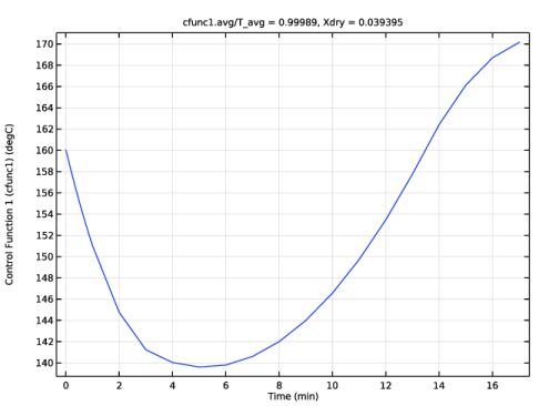
In the Settings window for Global, click Section toolbar in the upper-right corner of the y-Axis Data section. From the menu, choose Component 1 (comp1) > Definitions > Functions > cfunc1(s0) - Control Function 1 (cfunc1).
3
Locate the y-Axis Data section. In the table, enter the following settings:
Study 3: Optimal Control
Solver Configurations
In the Model Builder window, expand the Study 3: Optimal Control > Solver Configurations node.
Solution 3 (sol3)
1
In the Model Builder window, expand the Study 3: Optimal Control > Solver Configurations > Solution 3 (sol3) node, then click Optimization Solver 1.
2
In the Settings window for Optimization Solver, locate the Optimization Solver section.
3
Select the Move limits checkbox.
4
Click to expand the Advanced section. From the Compensate for nojac terms list, choose Off.
5
In the Model Builder window, expand the Study 3: Optimal Control > Solver Configurations > Solution 3 (sol3) > Optimization Solver 1 > Time-Dependent Solver 1 node, then click Advanced.
6
In the Settings window for Advanced, click to expand the Assembly Settings section.
7
Clear the Reuse sparsity pattern checkbox to get a cleaner log.
General Optimization
1
In the Model Builder window, under Study 3: Optimal Control click General Optimization.
2
In the Settings window for General Optimization, click to expand the Output section.
3
Select the Plot checkbox.
4
5
In the Study toolbar, click  Compute.
Use the last study to verify that neglecting the temperature variations effect on the flow is an acceptable assumption.
Step 1: Time Dependent
In the Model Builder window, right-click Step 1: Time Dependent and choose Copy.
Study 4: Validation
In the Model Builder window, right-click Study 4 and choose Paste Time Dependent.
1
In the Settings window for Time Dependent, locate the Physics and Variables Selection section.
2
In the Solve for column of the table, under Component 1 (comp1), select the checkbox for Laminar Flow (spf).
3
Click to expand the Values of Dependent Variables section. Find the Values of variables not solved for subsection. From the Method list, choose Solution.
4
From the Study list, choose Study 3: Optimal Control, Time Dependent.
5
Find the Initial values of variables solved for subsection. From the Settings list, choose User controlled.
6
From the Method list, choose Solution.
7
From the Study list, choose Study 3: Optimal Control, Time Dependent.
8
From the Time (min) list, choose First.
9
In the Model Builder window, click Study 4.
10
In the Settings window for Study, locate the Study Settings section.
11
Clear the Generate default plots checkbox.
12
In the Label text field, type Study 4: Validation.
13
In the Study toolbar, click  Compute.
Results
Global 2
1
In the Model Builder window, expand the Average Moisture Content on Dry Basis node.
2
Right-click Results > Average Moisture Content on Dry Basis > Global 1 and choose Duplicate.
3
In the Settings window for Global, locate the Data section.
4
From the Dataset list, choose Study 3: Optimal Control/Solution 3 (sol3).
5
Locate the y-Axis Data section. In the table, enter the following settings:
6
Click to expand the Legends section. Find the Include subsection. Clear the Solution checkbox.
7
Select the Description checkbox.
Global 3
1
Right-click Global 2 and choose Duplicate.
2
In the Settings window for Global, locate the Data section.
3
From the Dataset list, choose Study 4: Validation/Solution 4 (sol4).
4
Locate the y-Axis Data section. In the table, enter the following settings:
5
In the Average Moisture Content on Dry Basis toolbar, click  Plot.
The plot shows that the temperature variations do affect the flow, but the effect on the objective is marginal.