|
|
|
|
•
|
|
•
|


|
1
|
|
2
|
In the Select Physics tree, select Heat Transfer > Radiation > Radiation in Participating Media (rpm).
|
|
3
|
Click Add.
|
|
4
|
Click
|
|
5
|
|
6
|
Click
|
|
1
|
|
2
|
|
1
|
|
2
|
|
3
|
|
4
|
|
5
|
Click
|
|
1
|
|
2
|
|
3
|
Locate the Material Contents section. In the table, enter the following settings:
|
|
1
|
|
2
|
|
3
|
Locate the Geometric Entity Selection section. From the Geometric entity level list, choose Boundary.
|
|
4
|
|
5
|
Locate the Material Contents section. In the table, enter the following settings:
|
|
1
|
In the Model Builder window, under Component 1 (comp1) click Radiation in Participating Media (rpm).
|
|
2
|
In the Settings window for Radiation in Participating Media, locate the Participating Media Settings section.
|
|
3
|
Find the Radiation settings subsection. From the Discrete ordinates method list, choose S6 (48 directions).
|
|
1
|
In the Model Builder window, under Component 1 (comp1) > Radiation in Participating Media (rpm) click Participating Medium 1.
|
|
2
|
|
3
|
|
1
|
|
2
|
|
3
|
|
1
|
|
2
|
|
3
|
|
1
|
|
1
|
|
2
|
|
1
|
|
2
|
|
3
|
Click
|
|
1
|
|
2
|
|
3
|
|
4
|
|
5
|
|
1
|
|
2
|
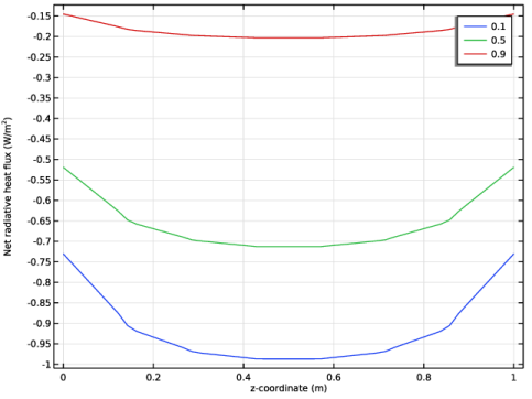
In the Settings window for 1D Plot Group, type Net Radiative Heat Flux vs. z, 1D in the Label text field.
|
|
1
|
|
2
|
|
4
|
|
5
|
In the Settings window for Line Graph, click Replace Expression in the upper-right corner of the y-Axis Data section. From the menu, choose Component 1 (comp1) > Radiation in Participating Media > Boundary fluxes > rpm.qr_net - Net radiative heat flux - W/m².
|
|
6
|
Click Replace Expression in the upper-right corner of the x-Axis Data section. From the menu, choose Component 1 (comp1) > Geometry > Coordinate > z - z-coordinate.
|
|
7
|
|
1
|
|
2
|
|
3
|
|
4
|
|
5
|
Select the y-axis label checkbox.
|
|
6
|
|
1
|
|
2
|
|
3
|
|
4
|
Click
|
|
1
|
|
2
|
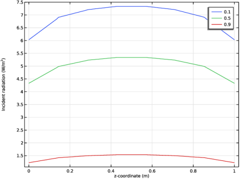
In the Settings window for 1D Plot Group, type Incident Radiation vs. z, 1D in the Label text field.
|
|
3
|
|
1
|
|
2
|
In the Settings window for Line Graph, click Replace Expression in the upper-right corner of the x-Axis Data section. From the menu, choose Component 1 (comp1) > Geometry > Coordinate > z - z-coordinate.
|
|
3
|
|
1
|
|
2
|
|
3
|
|
4
|
|
5
|
Select the y-axis label checkbox.
|
|
6
|
|
1
|
|
2
|
|
3
|
|
4
|
|
5
|
|
1
|
|
2
|
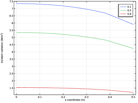
In the Settings window for 1D Plot Group, type Incident Radiation vs. x, 1D in the Label text field.
|
|
3
|
|
4
|
|
1
|
|
2
|
In the Settings window for Line Graph, click Replace Expression in the upper-right corner of the x-Axis Data section. From the menu, choose Component 1 (comp1) > Geometry > Coordinate > x - x-coordinate.
|
|
3
|
|
1
|
|
2
|
|
3
|
|
5
|
Locate the Surface Radiative Properties section. From the ε list, choose User defined. In the associated text field, type ew*(1-y/R).
|
|
1
|
|
2
|
|
3
|
Select the Modify model configuration for study step checkbox.
|
|
4
|
In the tree, select Component 1 (comp1) > Radiation in Participating Media (rpm) > Opaque Surface 2.
|
|
5
|
Click
|
|
1
|
|
2
|
Go to the Add Study window.
|
|
3
|
|
4
|
Click the Add Study button in the window toolbar.
|
|
5
|
|
1
|
|
2
|
|
3
|
Click
|
|
1
|
|
2
|
|
3
|
|
4
|
|
5
|
|
6
|
|
7
|
|
1
|
|
2
|
|
3
|
|
4
|
|
5
|
|
6
|
|
7
|
|
8
|
|
9
|
|
1
|
|
2
|
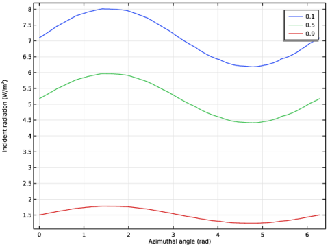
In the Settings window for 1D Plot Group, type Incident Radiation vs. Azimuthal Angle, 1D in the Label text field.
|
|
3
|
|
1
|
|
2
|
|
3
|
Select the Show legends checkbox.
|
|
1
|
|
2
|
|
3
|
|
4
|
Locate the Plot Settings section.
|
|
5
|
|
6
|
Select the y-axis label checkbox.
|
|
1
|
|
2
|
|
3
|
|
4
|
|
5
|
|
1
|
|
2
|
|
1
|
In the Model Builder window, under Component 1 (comp1) > Radiation in Participating Media (rpm) click Participating Medium 1.
|
|
2
|
|
3
|
|
4
|
|
1
|
|
2
|
Go to the Add Study window.
|
|
3
|
|
4
|
Click the Add Study button in the window toolbar.
|
|
5
|
|
1
|
|
2
|
|
3
|
Click
|
|
1
|
|
2
|
|
3
|
|
4
|
|
5
|
|
6
|
|
7
|
|
1
|
|
2
|
|
3
|
|
4
|
|
5
|
|
6
|
|
1
|
|
2
|
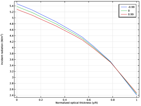
In the Settings window for 1D Plot Group, type Incident Radiation vs. Normalized Optical Thickness, 1D in the Label text field.
|
|
3
|
|
1
|
|
2
|
|
3
|
|
4
|
|
5
|
|
1
|
|
2
|
|
3
|
|
4
|
Locate the Plot Settings section.
|
|
5
|
Select the x-axis label checkbox. In the associated text field, type Normalized optical thickness (y/R).
|
|
6
|
Select the y-axis label checkbox.
|
|
7
|