|
|
|
|
•
|
|
•
|
|
•
|
Add a Gravity node to account for gravity effects.
|

|
1
|
|
2
|
|
3
|
Click Add.
|
|
4
|
Click
|
|
5
|
|
6
|
Click
|
|
1
|
|
2
|
|
3
|
|
4
|
|
5
|
|
6
|
Click
|
|
1
|
|
2
|
|
3
|
|
4
|
|
5
|
|
6
|
|
7
|
Click
|
|
1
|
|
2
|
|
1
|
In the Model Builder window, under Component 1 (comp1) > Solid Mechanics (solid) click Linear Elastic Material 1.
|
|
2
|
|
3
|
|
1
|
|
1
|
|
1
|
|
1
|
|
2
|
|
3
|
|
1
|
|
2
|
|
3
|
|
1
|
|
3
|
|
4
|
|
1
|
In the Model Builder window, under Component 1 (comp1) right-click Materials and choose Blank Material.
|
|
2
|
|
1
|
|
2
|
|
3
|
|
1
|
|
3
|
|
4
|
|
5
|
|
1
|
|
2
|
|
1
|
|
2
|
|
3
|
Select the Modify model configuration for study step checkbox.
|
|
4
|
In the tree, select Component 1 (comp1) > Solid Mechanics (solid) > Linear Elastic Material 1 > Soil Plasticity 1, Component 1 (comp1) > Solid Mechanics (solid) > Linear Elastic Material 1 > Initial Stress and Strain 1, and Component 1 (comp1) > Solid Mechanics (solid) > Linear Elastic Material 1 > Activation 1.
|
|
5
|
Click
|
|
1
|
|
2
|
Go to the Add Study window.
|
|
3
|
|
4
|
Click the Add Study button in the window toolbar.
|
|
5
|
|
1
|
|
2
|
|
1
|
|
2
|
|
3
|
|
4
|
|
5
|
|
1
|
In the Model Builder window, expand the Results > Stress (solid) 1 node, then click Stress (solid) 1.
|
|
2
|
|
1
|
In the Model Builder window, expand the Results > Stress: After Excavation > Surface 1 node, then click Deformation.
|
|
2
|
|
3
|
|
1
|
|
2
|
|
3
|
|
4
|
|
5
|
|
1
|
|
2
|
Go to the Result Templates window.
|
|
3
|
In the tree, select Study: After Excavation/Solution 2 (sol2) > Solid Mechanics > Equivalent Plastic Strain (solid).
|
|
4
|
Click the Add Result Template button in the window toolbar.
|
|
5
|
|
1
|
In the Model Builder window, expand the Plastic Region: After Excavation node, then click Surface 1.
|
|
2
|
|
3
|
|
4
|
Clear the Description checkbox.
|
|
5
|
|
1
|
|
2
|
|
3
|
|
4
|
|
5
|
|
1
|
|
2
|
|
3
|
|
5
|
|
1
|
|
2
|
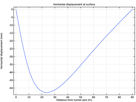
In the Settings window for 1D Plot Group, type Horizontal Displacement: After Excavation in the Label text field.
|
|
3
|
|
4
|
|
5
|
|
6
|
Locate the Plot Settings section.
|
|
7
|
|
8
|
|
1
|
|
3
|
|
4
|
|
5
|
|
6
|
|
1
|
In the Model Builder window, right-click Horizontal Displacement: After Excavation and choose Duplicate.
|
|
2
|
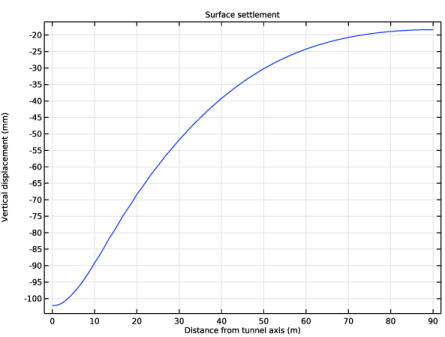
In the Settings window for 1D Plot Group, type Vertical Displacement: After Excavation in the Label text field.
|
|
3
|
|
4
|
|
1
|
In the Model Builder window, expand the Vertical Displacement: After Excavation node, then click Line Graph 1.
|
|
2
|
|
3
|
|
4
|