|
|
|

|
1
|
|
2
|
|
3
|
Right-click and choose Add Physics.
|
|
4
|
Click
|
|
5
|
|
6
|
Click
|
|
1
|
|
2
|
|
3
|
Click
|
|
4
|
Browse to the model’s Application Libraries folder and double-click the file notched_beam_damage_parameters.txt.
|
|
1
|
|
2
|
|
3
|
|
4
|
|
5
|
|
6
|
|
7
|
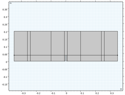
Click to expand the Layers section. Add a number of subdivisions to the beam in order to facilitate application of loads and constraints, as well as mesh control.
|
|
8
|
Select the Layers to the left checkbox.
|
|
9
|
Clear the Layers on bottom checkbox.
|
|
1
|
|
2
|
|
3
|
|
4
|
|
1
|
|
2
|
|
3
|
|
4
|
|
5
|
|
6
|
|
1
|
|
2
|
Click in the Graphics window and then press Ctrl+A to select both objects.
|
|
3
|
Select the object r1 only.
|
|
4
|
|
5
|
|
6
|
|
7
|
Select the object r2 only.
|
|
8
|
Click
|
|
1
|
|
2
|
|
3
|
|
4
|
|
5
|
|
6
|
|
1
|
|
2
|
On the object fin, select Boundaries 4, 6, 8, 9, 11, 13, 14, 16, 18, 19, 21, 23, 24, 27, 30, 31, 33, 34, 36, 38, 39, 41, 43, 44, 46, 48, and 49 only.
|
|
3
|
|
4
|
Clear the Include adjacent vertices checkbox.
|
|
1
|
|
2
|
On the object mce1, select Points 2, 5, 6, 8–14, 20, 21, 23–25, 27, 28, 30, 31, and 33 only.
|
|
3
|
|
1
|
|
2
|
|
3
|
|
4
|
|
1
|
|
2
|
In the Settings window for Average, type Crack Mouth Opening Displacement, Left in the Label text field.
|
|
3
|
|
4
|
|
1
|
|
2
|
|
1
|
|
2
|
|
3
|
From the list, choose Plane stress.
|
|
4
|
|
1
|
|
2
|
|
1
|
|
2
|
|
3
|
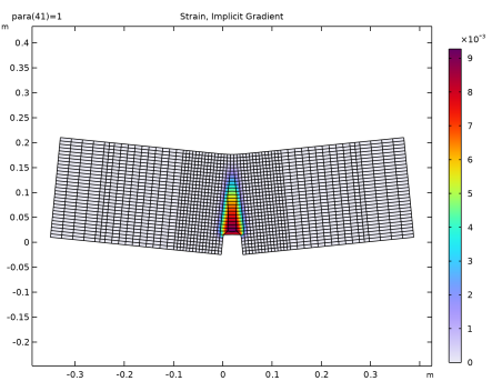
Locate the Damage section. Find the Spatial regularization method subsection. From the list, choose Implicit gradient.
|
|
4
|
|
5
|
|
1
|
|
3
|
In the Settings window for Rigid Connector, locate the Prescribed Displacement at Center of Rotation section.
|
|
4
|
Select the Prescribed in x direction checkbox.
|
|
5
|
Select the Prescribed in y direction checkbox.
|
|
1
|
|
3
|
In the Settings window for Rigid Connector, locate the Prescribed Displacement at Center of Rotation section.
|
|
4
|
Select the Prescribed in y direction checkbox.
|
|
1
|
|
3
|
|
4
|
|
5
|
|
6
|
|
7
|
In the Show More Options dialog, in the tree, select the checkbox for the node Physics > Equation Contributions.
|
|
8
|
|
9
|
Click OK.
|
|
1
|
|
2
|
|
3
|
Locate the Global Equations section. In the table, enter the following settings:
|
|
4
|
|
5
|
|
6
|
|
7
|
Click OK.
|
|
8
|
|
9
|
Click
|
|
10
|
|
11
|
|
12
|
Click OK.
|
|
1
|
|
2
|
|
3
|
|
1
|
In the Model Builder window, under Component 1 (comp1) right-click Materials and choose Blank Material.
|
|
2
|
|
1
|
|
2
|
|
3
|
Click the Custom button.
|
|
4
|
|
1
|
|
2
|
|
3
|
|
1
|
|
2
|
|
3
|
|
1
|
|
2
|
|
3
|
|
1
|
|
2
|
|
3
|
|
5
|
|
1
|
|
2
|
|
3
|
Select the Modify model configuration for study step checkbox.
|
|
4
|
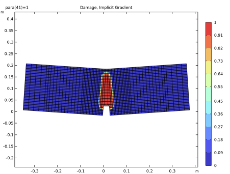
In the tree, select Component 1 (comp1) > Solid Mechanics (solid) > Linear Elastic Material 1 > Damage: Implicit Gradient.
|
|
5
|
Right-click and choose Disable.
|
|
6
|
|
7
|
|
8
|
|
9
|
Click
|
|
11
|
|
12
|
|
13
|
|
1
|
|
2
|
|
3
|
Click
|
|
4
|
|
5
|
Click OK.
|
|
6
|
|
8
|
Click
|
|
9
|
|
10
|
Click OK.
|
|
11
|
|
13
|
Click
|
|
14
|
|
15
|
Click OK.
|
|
16
|
|
18
|
Click
|
|
1
|
|
2
|
Go to the Result Templates window.
|
|
3
|
|
4
|
Click the Add Result Template button in the window toolbar.
|
|
5
|
|
1
|
|
2
|
|
3
|
|
1
|
|
2
|
|
3
|
|
4
|
|
1
|
|
2
|
|
3
|
|
4
|
|
1
|
|
2
|
|
1
|
|
2
|
|
3
|
|
4
|
|
1
|
|
2
|
In the Settings window for Surface, click Replace Expression in the upper-right corner of the Expression section. From the menu, choose Component 1 (comp1) > Solid Mechanics > Damage > solid.kappadmgGp - Maximum value of equivalent strain - 1.
|
|
3
|
|
4
|
|
1
|
|
2
|
|
3
|
|
4
|
|
1
|
|
2
|
|
1
|
|
2
|
Go to the Add Study window.
|
|
3
|
|
4
|
Right-click and choose Add Study.
|
|
5
|
|
1
|
|
2
|
Select the Auxiliary sweep checkbox.
|
|
3
|
Click
|
|
5
|
|
6
|
|
7
|
|
8
|
|
1
|
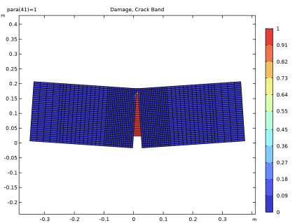
In the Model Builder window, under Results, Ctrl-click to select Damage, Crack Band and Strain, Crack Band.
|
|
2
|
Right-click and choose Duplicate.
|
|
1
|
|
2
|
|
3
|
|
1
|
|
2
|
|
3
|
|
4
|
|
5
|
|
1
|
|
2
|
|
1
|
|
2
|
|
4
|
|
5
|
|
6
|
|
7
|
|
9
|
|
10
|
|
1
|
|
2
|
|
3
|
|
4
|
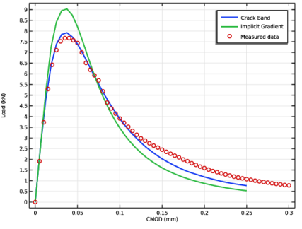
Locate the Legends section. In the table, enter the following settings:
|
|
5
|
|
1
|
|
2
|
|
3
|
|
4
|
Locate the Plot Settings section.
|
|
5
|
|
6
|
|
7
|
|
1
|
|
2
|
|
3
|
|
1
|
|
2
|
|
3
|
|
1
|
|
2
|
|
3
|
|
1
|
|
2
|
|
3
|
Click
|
|
4
|
Browse to the model’s Application Libraries folder and double-click the file notched_beam_damage_measured.txt.
|
|
1
|
Go to the Table 1 window.
|
|
2
|
Click the Table Graph button in the window toolbar.
|
|
1
|
|
2
|
|
3
|
|
4
|
|
5
|
|
6
|
|
8
|
|
1
|
|
2
|
|
3
|
|
4
|
|
5
|
|
1
|
|
2
|
|
3
|
|
1
|
|
2
|
|
1
|
|
2
|
|
3
|
|
4
|
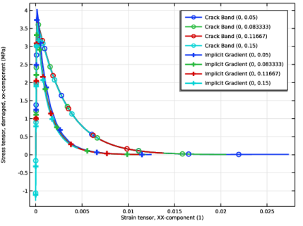
Click Replace Expression in the upper-right corner of the y-Axis Data section. From the menu, choose Component 1 (comp1) > Solid Mechanics > Damage > Stress tensor, damaged (spatial frame) - N/m² > solid.sdGpxx - Stress tensor, damaged, xx-component.
|
|
5
|
|
6
|
Click Replace Expression in the upper-right corner of the x-Axis Data section. From the menu, choose Component 1 (comp1) > Solid Mechanics > Strain > Strain tensor (material and geometry frames) > solid.eXX - Strain tensor, XX-component.
|
|
7
|
|
8
|
|
9
|
|
10
|
|
11
|
|
12
|
|
1
|
|
2
|
|
3
|
|
4
|
Locate the Legends section. Find the Prefix and suffix subsection. In the Prefix text field, type Implicit Gradient .
|
|
5
|
|
6
|
|
1
|
|
2
|
|
3
|