|
|
|
|
1
|
|
2
|
|
3
|
Click Add.
|
|
4
|
In the Concentrations (mol/m³) table, enter the following settings:
|
|
5
|
Click
|
|
6
|
|
7
|
Click
|
|
1
|
|
2
|
|
3
|
Click
|
|
4
|
Browse to the model’s Application Libraries folder and double-click the file microdisk_voltammetry_parameters.txt.
|
|
1
|
|
2
|
|
3
|
|
4
|
|
1
|
|
2
|
|
3
|
|
1
|
In the Model Builder window, under Component 1 (comp1) > Geometry 1 right-click Circle 1 (c1) and choose Duplicate.
|
|
2
|
|
3
|
|
4
|
|
5
|
|
6
|
|
1
|
|
1
|
|
2
|
|
3
|
|
4
|
|
1
|
|
2
|
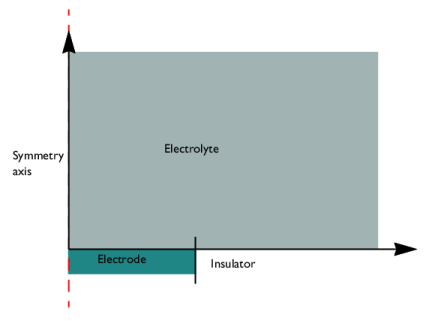
In the Settings window for Electrode Surface, locate the Electrode Phase Potential Condition section.
|
|
3
|
|
4
|
|
1
|
|
2
|
|
3
|
|
4
|
|
5
|
|
6
|
|
1
|
|
3
|
|
4
|
Select the Species cRed checkbox.
|
|
5
|
|
6
|
Select the Species cOx checkbox.
|
|
1
|
|
2
|
|
3
|
|
1
|
In the Model Builder window, under Component 1 (comp1) right-click Mesh 1 and choose Edit Physics-Induced Sequence.
|
|
1
|
|
2
|
|
3
|
|
4
|
Click to expand the Element Size Parameters section. In the Maximum element growth rate text field, type 1.1.
|
|
1
|
|
2
|
|
3
|
|
1
|
|
2
|
|
3
|
|
5
|
|
6
|
Locate the Element Size Parameters section.
|
|
7
|
|
1
|
|
2
|
|
3
|
|
5
|
|
1
|
|
2
|
|
3
|
Click
|
|
5
|
|
1
|
In the Model Builder window, expand the Component 1 (comp1) > Definitions > View 1 node, then click Axis.
|
|
2
|
|
3
|
|
4
|
|
5
|
|
6
|
|
7
|
Click
|
|
1
|
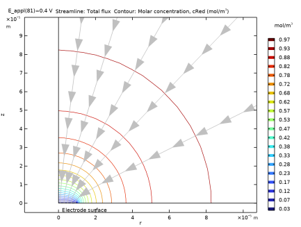
In the Model Builder window, expand the Results > Concentration, Red (tcd) node, then click Concentration, Red (tcd).
|
|
2
|
|
3
|
|
4
|
|
5
|
|
1
|
|
2
|
|
3
|
|
4
|
|
5
|
|
1
|
|
2
|
|
3
|
|
4
|
|
5
|
|
7
|
Locate the Coloring and Style section. Find the Point style subsection. From the Arrow length list, choose Normalized.
|
|
8
|
|
1
|
|
2
|
|
3
|
|
4
|
|
5
|
|
1
|
|
2
|
|
3
|
|
4
|
|
1
|
|
2
|
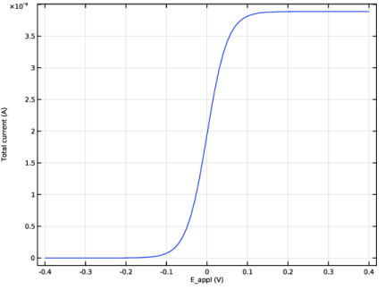
In the Settings window for Global, click Replace Expression in the upper-right corner of the y-Axis Data section. From the menu, choose Component 1 (comp1) > Electroanalysis > Electrode kinetics > tcd.Itot_es1 - Total current - A.
|
|
3
|