PDF

Ladder Frame Geometry
Introduction
For geometries with a high aspect ratio in one direction, shell elements are preferred compared to solid elements. Using the Design Module, you can convert a solid geometry representation to a surface object by removing its thickness. In addition, the Design Module includes defeaturing tools that can be applied to delete geometric details that are not relevant for the analysis. This example generates the shell geometry of a ladder frame, or ladder chassis, from an imported solid structure for the eigenfrequency and static analyses described in the Ladder Frame model located in the Structural Mechanics Module Application Library.
Model Definition
The ladder frame geometry is imported from a STEP file as solid objects. The step-by-step instructions demonstrate how to generate a shell model from the imported solids.
Read on to find out more about the following topics:
Application Library path: Design_Module/Tutorial_Examples/ladder_frame_geometry
Modeling Instructions
From the File menu, choose New.
New
In the New window, click  Blank Model.
Add Component
In the Home toolbar, click  Add Component and choose 3D.
Geometry 1
1
In the Settings window for Geometry, locate the Advanced section.
2
From the Geometry representation list, choose CAD kernel.
3
Select the Design Module Boolean operations checkbox.
Import 1 (imp1)
1
In the Geometry toolbar, click  Import.
2
In the Settings window for Import, locate the Source section.
3
Click  Browse.
4
5
Locate the Simplify and Repair section. Select the Remove redundant edges and vertices checkbox.
6
Click  Build Selected.
One way to retrieve the thickness of the beams is to use the Distance Measurement tools.
Distance Measurement 1 (dm1)
1
In the Geometry toolbar, click  Measurements and choose Distance Measurement.
2
On the object imp1.id5, select Point 44 only.
3
In the Settings window for Distance Measurement, locate the Geometric Entity Selection section.
4
Click to select the  Activate Selection toggle button for Second entity.
5
On the object imp1.id5, select Point 43 only.
6
Locate the Parameter Names section. In the Distance text field, type th1.
Distance Measurement 2 (dm2)
1
In the Geometry toolbar, click  Measurements and choose Distance Measurement.
2
On the object imp1.id101, select Point 65 only.
3
In the Settings window for Distance Measurement, locate the Geometric Entity Selection section.
4
Click to select the  Activate Selection toggle button for Second entity.
5
On the object imp1.id101, select Point 67 only.
6
Locate the Parameter Names section. In the Distance text field, type th2.
Longitudinal members
1
In the Geometry toolbar, click  Selections and choose Explicit Selection.
2
In the Settings window for Explicit Selection, type Longitudinal members in the Label text field.
3
Locate the Entities to Select section. From the Geometric entity level list, choose Boundary.
4
Select the Group by continuous tangent checkbox.
5
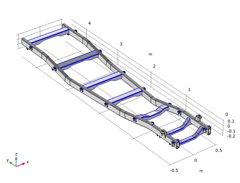
In the Graphics window, select the outer boundaries of the longitudinal members. By using Group by continuous tangent, it is sufficient to select one face for each object. The contributing boundaries are shown in the figure below:
6
In the Geometry toolbar, click  Defeaturing and Repair and choose Delete Fillets.
All objects are automatically added to the Input objects list.
7
In the Model Builder window, click Geometry 1.
8
Remove the longitudinal members imp1.id5, imp1.id8, imp1.id92, and imp1.id95 from the list.
9
In the Tools window for Delete Fillets, locate the Delete Fillets section.
10
In the Maximum fillet radius text field, type 7[mm].
11
Click Find Fillets.
12
Click Delete All.
Convert the transverse beams and the brackets to a midsurface representation.
Midsurface 1 (mid1)
1
In the Geometry toolbar, click  Conversions and choose Midsurface.
2
Click the  Select All button in the Graphics toolbar.
3
In the Graphics window, click on the longitudinal members to remove them from the selection list.
In the table below you can find the corresponding selected objects:
4
In the Settings window for Midsurface, click  Build Selected.
The longitudinal members are not represented by the midsurface but by the top surface.
Extract 1 (extract1)
1
In the Geometry toolbar, click  Extract.
2
In the Settings window for Extract, locate the Entities or Objects to Extract section.
3
From the Selection list, choose Longitudinal members.
4
From the Input object handling list, choose Remove.
5
Click  Build Selected.
Union 1 (uni1)
1
In the Geometry toolbar, click  Booleans and Partitions and choose Union.
2
Click the  Select All button in the Graphics toolbar.
3
In the Settings window for Union, click  Build Selected.
Cross members
1
In the Geometry toolbar, click  Selections and choose Box Selection.
2
In the Settings window for Box Selection, type Cross members in the Label text field.
3
Locate the Geometric Entity Level section. From the Level list, choose Boundary.
4
Select the Group by continuous tangent checkbox.
5
Locate the Box Limits section. In the x minimum text field, type 0.
6
In the x maximum text field, type 0.
Clean up the geometry, removing unnecessary details.
Remove Details 1 (rmd1)
1
In the Geometry toolbar, click  Virtual Operations and choose Remove Details.
2
In the Settings window for Remove Details, click  Build Selected.