|
|
|
|
1
|
|
2
|
|
3
|
Click Add.
|
|
4
|
Click
|
|
5
|
|
6
|
Click
|
|
1
|
|
2
|
|
1
|
|
2
|
|
3
|
Click
|
|
4
|
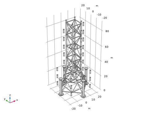
Browse to the model’s Application Libraries folder and double-click the file oil_platform.mphbin.
|
|
5
|
Click
|
|
6
|
Click to expand the Selections of Resulting Entities section. Select the Resulting objects selection checkbox.
|
|
7
|
|
8
|
Select the Individual object selections checkbox.
|
|
9
|
|
10
|
|
1
|
|
2
|
|
3
|
|
4
|
|
5
|
Click
|
|
6
|
|
1
|
|
2
|
|
3
|
|
4
|
|
1
|
|
2
|
|
3
|
|
4
|
|
5
|
|
6
|
Click
|
|
7
|
|
8
|
|
9
|
|
10
|
Clear the Automatic detection of small details checkbox.
|
|
11
|
|
1
|
|
2
|
|
4
|
|
5
|
|
1
|
|
2
|
|
3
|
|
4
|
|
5
|
|
6
|
Click OK.
|
|
7
|
|
8
|
|
9
|
|
10
|
Click OK.
|
|
1
|
|
2
|
Go to the Add Material window.
|
|
3
|
|
4
|
Right-click and choose Add to Component 1 (comp1).
|
|
5
|
|
1
|
|
2
|
|
3
|
|
1
|
In the Model Builder window, under Component 1 (comp1) > Cathodic Protection (cp) click Electrolyte 1.
|
|
2
|
|
3
|
|
1
|
|
2
|
In the Settings window for Electrode Surface, type Electrode Surface - Anodes in the Label text field.
|
|
3
|
|
1
|
|
2
|
|
3
|
|
4
|
Locate the Electrode Kinetics section. From the Kinetics expression type list, choose Primary condition (thermodynamic equilibrium).
|
|
1
|
|
2
|
In the Settings window for Protected Metal Surface, type Protected Metal Surface - Steel in the Label text field.
|
|
3
|
|
4
|
|
1
|
|
2
|
|
3
|
|
4
|
|
1
|
|
2
|
|
3
|
Click the Custom button.
|
|
4
|
|
5
|
|
6
|
|
1
|
|
2
|
|
3
|
|
4
|
Click
|
|
5
|
|
6
|
Click OK.
|
|
1
|
|
2
|
|
3
|
Click the Custom button.
|
|
4
|
Locate the Element Size Parameters section.
|
|
5
|
|
6
|
Click
|
|
7
|
|
1
|
|
2
|
|
3
|
|
1
|
|
1
|
|
2
|
|
3
|
|
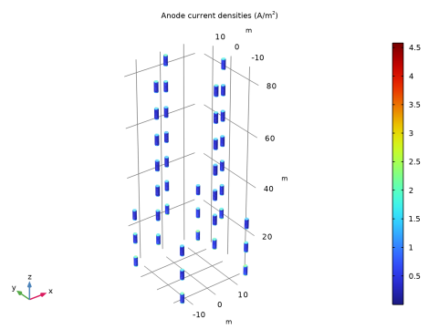
1
|
|
2
|
In the Settings window for 3D Plot Group, type Anode current densities (cp) in the Label text field.
|
|
3
|
|
4
|
|
5
|
|
1
|
|
2
|
|
1
|
|
2
|
|
3
|
|
1
|
|
2
|
|
3
|
|
4
|
|
5
|
|
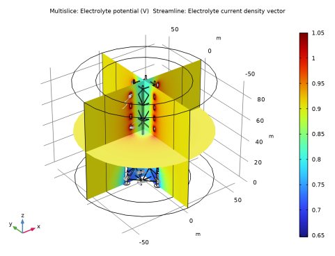
1
|
In the Model Builder window, under Results click Electrode Potential with Respect to Adjacent Reference (cp).
|
|
2
|
|
3
|
|
4
|
|
5
|
|
1
|
|
2
|
|
1
|
|
2
|
|
3
|
|
4
|
|
5
|
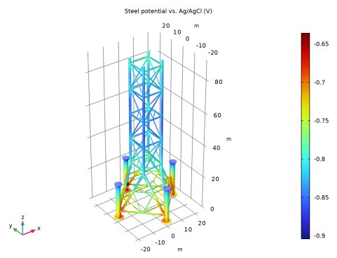
|
1
|
|
2
|
Expand the Steel potential (cp) 1 node.
|
|
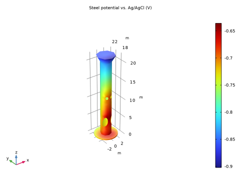
1
|
In the Model Builder window, expand the Results > Steel potential (cp) 1 > Surface 1 node, then click Selection 1.
|
|
2
|
|
3
|
|
4
|
Click
|
|
5
|
Click
|
|
6
|
|
7
|
Click OK.
|
|
1
|
|
2
|
In the Settings window for 3D Plot Group, type Steel potential, close-up (cp) in the Label text field.
|
|
3
|
|
4
|