|
|
|

|
1
|
|
2
|
In the Select Physics tree, select Fluid Flow > Multiphase Flow > Mixture Model > Mixture Model, Laminar Flow (mm).
|
|
3
|
Click Add.
|
|
4
|
Click
|
|
5
|
|
6
|
Click
|
|
1
|
|
2
|
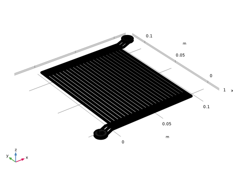
Browse to the model’s Application Libraries folder and double-click the file pem_electrolyzer_geom_sequence.mph.
|
|
3
|
|
4
|
|
1
|
|
2
|
|
1
|
|
2
|
|
3
|
|
1
|
|
2
|
|
3
|
Click
|
|
4
|
Browse to the model’s Application Libraries folder and double-click the file pem_electrolyzer_parameters.txt.
|
|
1
|
In the Model Builder window, under Component 1 (comp1) right-click Definitions and choose Variables.
|
|
2
|
|
3
|
Click
|
|
4
|
Browse to the model’s Application Libraries folder and double-click the file pem_electrolyzer_variables.txt.
|
|
1
|
|
2
|
|
3
|
|
4
|
|
5
|
|
6
|
|
7
|
|
1
|
|
2
|
|
3
|
Select the Cutoff checkbox.
|
|
4
|
|
1
|
|
2
|
Go to the Add Material window.
|
|
3
|
|
4
|
Right-click and choose Add to Component 1 (comp1).
|
|
5
|
|
6
|
Right-click and choose Add to Component 1 (comp1).
|
|
7
|
|
1
|
|
2
|
|
3
|
|
1
|
In the Model Builder window, under Component 1 (comp1) > Mixture Model, Laminar Flow (mm) click Mixture Properties 1.
|
|
2
|
|
3
|
|
4
|
|
5
|
Locate the Dispersed Phase Properties section. From the ρd list, choose User defined. In the associated text field, type rhoO2.
|
|
6
|
|
7
|
|
1
|
|
2
|
|
3
|
|
4
|
|
1
|
|
2
|
In the Settings window for Inlet, type Inlet - Electrode Surface Oxygen Evolution in the Label text field.
|
|
3
|
|
4
|
|
5
|
Locate the Dispersed Phase Boundary Condition section. From the Dispersed phase boundary condition list, choose Dispersed phase flux.
|
|
6
|
|
1
|
|
2
|
|
3
|
|
1
|
|
2
|
|
3
|
|
4
|
|
1
|
|
2
|
|
3
|
From the list, choose Physics-controlled mesh.
|
|
1
|
|
2
|
|
3
|
|
1
|
|
2
|
|
3
|
|
4
|
|
5
|
Click to expand the Source Faces section. From the Selection list, choose Inlets to Electrode Channels.
|
|
6
|
Click to expand the Destination Faces section. From the Selection list, choose Outlets from Electrode Channels.
|
|
1
|
|
2
|
|
3
|
|
4
|
|
1
|
|
2
|
|
3
|
Click the Custom button.
|
|
4
|
Locate the Geometric Entity Selection section. From the Geometric entity level list, choose Boundary.
|
|
5
|
|
6
|
Locate the Element Size Parameters section.
|
|
7
|
|
8
|
|
1
|
|
2
|
|
3
|
|
4
|
|
5
|
|
1
|
|
2
|
|
3
|
Click the Custom button.
|
|
4
|
Locate the Element Size Parameters section.
|
|
5
|
|
6
|
|
1
|
|
2
|
|
3
|
|
1
|
|
2
|
|
3
|
Click the Custom button.
|
|
4
|
Locate the Element Size Parameters section.
|
|
5
|
|
6
|
|
1
|
|
2
|
|
3
|
|
4
|
|
1
|
|
2
|
|
3
|
|
4
|
|
5
|
|
6
|
|
7
|
|
1
|
|
2
|
|
1
|
|
2
|
|
3
|
|
1
|
|
2
|
|
3
|
|
4
|
|
5
|
In the Model Builder window, expand the Study 1 > Solver Configurations > Solution 1 (sol1) > Dependent Variables 1 node, then click Volume Fraction, Dispersed Phase (comp1.phid).
|
|
6
|
|
7
|
Clear the Solve for this field checkbox.
|
|
8
|
In the Model Builder window, under Study 1 > Solver Configurations > Solution 1 (sol1) > Dependent Variables 1 click Squared Slip Velocity (comp1.slipvel).
|
|
9
|
|
10
|
Clear the Solve for this field checkbox.
|
|
11
|
In the Model Builder window, expand the Study 1 > Solver Configurations > Solution 1 (sol1) > Dependent Variables 2 node, then click Velocity Field, Mixture (comp1.j).
|
|
12
|
|
13
|
|
14
|
In the Model Builder window, under Study 1 > Solver Configurations > Solution 1 (sol1) > Dependent Variables 2 click Pressure (comp1.p).
|
|
15
|
|
16
|
|
17
|
In the Model Builder window, under Study 1 > Solver Configurations > Solution 1 (sol1) > Dependent Variables 2 click Volume Fraction, Dispersed Phase (comp1.phid).
|
|
18
|
|
19
|
|
20
|
|
21
|
|
22
|
Clear the Generate default plots checkbox.
|
|
23
|
|
1
|
|
2
|
|
1
|
|
2
|
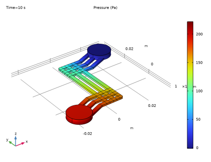
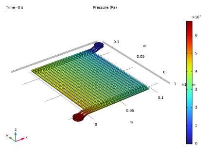
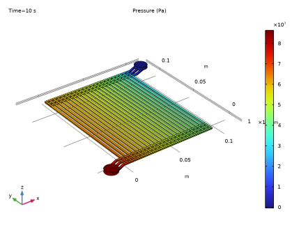
In the Settings window for Surface, click Replace Expression in the upper-right corner of the Expression section. From the menu, choose Component 1 (comp1) > Mixture Model, Laminar Flow > Velocity and pressure > p - Pressure - Pa.
|
|
3
|
|
1
|
|
2
|
|
1
|
|
2
|
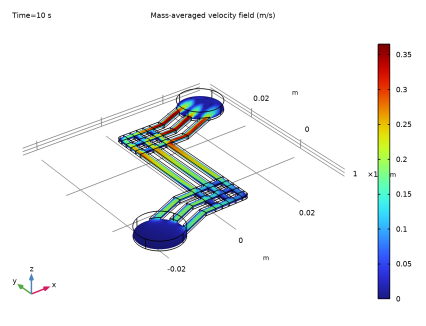
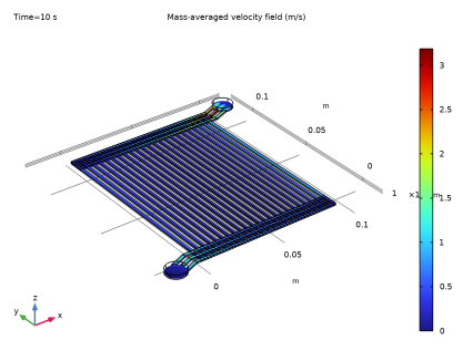
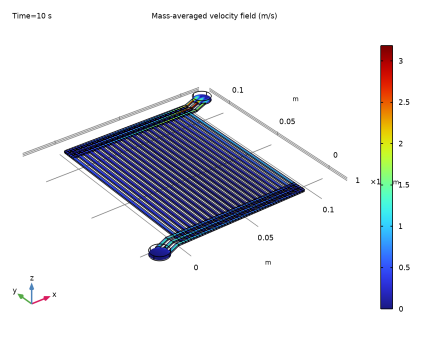
In the Settings window for Slice, click Replace Expression in the upper-right corner of the Expression section. From the menu, choose Component 1 (comp1) > Mixture Model, Laminar Flow > Velocity and pressure > mm.U - Mass-averaged velocity field - m/s.
|
|
3
|
|
4
|
|
5
|
|
6
|
|
1
|
|
2
|
|
1
|
|
2
|
|
3
|
|
1
|
|
2
|
|
3
|
|
4
|
|
5
|
|
6
|
|
7
|
|
8
|
|
1
|
|
2
|
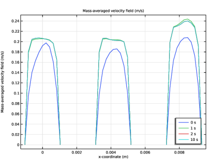
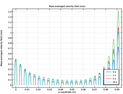
In the Settings window for 1D Plot Group, type Velocity in Electrode Channels in the Label text field.
|
|
3
|
|
1
|
|
2
|
In the Settings window for Line Graph, click Replace Expression in the upper-right corner of the y-Axis Data section. From the menu, choose Component 1 (comp1) > Mixture Model, Laminar Flow > Velocity and pressure > mm.U - Mass-averaged velocity field - m/s.
|
|
3
|
|
4
|
|
5
|
|
1
|
|
2
|
|
3
|
|
4
|
|
1
|
|
2
|
|
1
|
|
2
|
|
3
|
|
1
|
|
2
|
|
3
|
|
4
|
|
5
|
|
1
|
In the Model Builder window, under Study 1 > Solver Configurations right-click Solution 1 (sol1) and choose Solution > Copy.
|
|
1
|
In the Model Builder window, under Study 1 > Solver Configurations click Solution 1 - Copy 1 (sol3).
|
|
2
|
|
1
|
|
2
|
|
3
|
|
4
|
In the Model Builder window, expand the Study 1 > Solver Configurations > Solution 1 (sol1) > Dependent Variables 1 node, then click Volume Fraction, Dispersed Phase (comp1.phid).
|
|
5
|
|
6
|
Clear the Solve for this field checkbox.
|
|
7
|
|
8
|
|
9
|
Clear the Solve for this field checkbox.
|
|
10
|
In the Model Builder window, expand the Study 1 > Solver Configurations > Solution 1 (sol1) > Dependent Variables 2 node, then click Volume Fraction, Dispersed Phase (comp1.phid).
|
|
11
|
|
12
|
|
13
|
|
14
|
|
15
|
|
16
|
|
1
|
|
2
|
|
3
|
Select the Plot checkbox.
|
|
5
|
|
6
|
|
1
|
|
2
|
|
3
|
|
4
|
|
5
|
|
1
|
|
2
|
|
1
|
|
2
|
|
1
|
|
2
|
|
1
|
|
2
|
Click
|
|
1
|
|
2
|
|
3
|
Click
|
|
4
|
Browse to the model’s Application Libraries folder and double-click the file pem_electrolyzer_geom_sequence_parameters.txt.
|
|
1
|
|
2
|
|
3
|
|
4
|
Click
|
|
5
|
|
1
|
|
2
|
|
3
|
|
4
|
|
5
|
|
6
|
Click
|
|
1
|
|
2
|
|
3
|
|
4
|
|
5
|
|
6
|
|
7
|
Click
|
|
8
|
|
1
|
|
2
|
|
3
|
|
4
|
|
5
|
|
6
|
Click
|
|
1
|
|
2
|
|
4
|
Click
|
|
1
|
|
2
|
Select the object arr1(1,3,1) only.
|
|
3
|
|
4
|
|
5
|
|
6
|
|
7
|
|
8
|
Click
|
|
1
|
|
2
|
|
4
|
Click
|
|
1
|
|
2
|
|
3
|
|
4
|
|
5
|
Select the object pol2 only.
|
|
6
|
Click
|
|
1
|
|
2
|
Select the object dif1 only.
|
|
3
|
|
4
|
|
5
|
|
6
|
|
7
|
Click
|
|
1
|
|
2
|
Click in the Graphics window and then press Ctrl+A to select both objects.
|
|
3
|
|
1
|
|
2
|
Select the object uni1 only.
|
|
3
|
|
4
|
|
5
|
|
6
|
Click
|
|
7
|
|
1
|
|
2
|
|
3
|
|
4
|
|
5
|
|
6
|
|
7
|
Click
|
|
1
|
|
2
|
|
3
|
Select the object r3 only.
|
|
4
|
|
5
|
|
6
|
|
7
|
Click
|
|
1
|
|
2
|
|
3
|
|
4
|
|
5
|
|
6
|
|
1
|
|
2
|
Select the object r4 only.
|
|
3
|
|
4
|
|
5
|
|
6
|
Click
|
|
1
|
|
2
|
|
3
|
|
4
|
|
5
|
|
6
|
Click
|
|
1
|
|
2
|
Select the object mov1 only.
|
|
3
|
|
4
|
|
5
|
|
6
|
|
7
|
|
8
|
Click
|
|
1
|
|
2
|
|
3
|
Click in the Graphics window and then press Ctrl+A to select all objects.
|
|
1
|
|
2
|
|
3
|
|
4
|
|
5
|
|
6
|
Click
|
|
1
|
|
2
|
|
3
|
|
4
|
|
5
|
|
6
|
Click
|
|
1
|
|
2
|
|
3
|
|
4
|
|
5
|
Click
|
|
1
|
Right-click Component 1 (comp1) > Geometry 1 > Work Plane 1 (wp1) > Plane Geometry > Fillet 1 (fil1) and choose Duplicate.
|
|
2
|
|
3
|
|
4
|
|
5
|
Click
|
|
1
|
|
2
|
|
4
|
Click
|
|
1
|
|
2
|
|
3
|
|
4
|
|
5
|
Click
|
|
1
|
|
2
|
Select the object cyl1 only.
|
|
3
|
|
4
|
|
5
|
|
6
|
|
7
|
Click
|
|
1
|
|
2
|
Select the object rot1 only.
|
|
3
|
|
4
|
|
5
|
|
6
|
Click
|
|
1
|
|
2
|
Select the object mov1 only.
|
|
3
|
|
4
|
Select the Keep input objects checkbox.
|
|
5
|
|
6
|
|
7
|
|
8
|
Click
|
|
1
|
|
2
|
|
3
|
|
1
|
|
2
|
|
3
|
|
4
|
|
5
|
|
6
|
Click
|
|
1
|
|
2
|
|
3
|
|
4
|
|
5
|
|
1
|
|
2
|
In the Settings window for Box Selection, type Channels Above Electrode Surface in the Label text field.
|
|
3
|
|
4
|
|
5
|
|
1
|
|
2
|
|
3
|
|
4
|
|
5
|
|
6
|
|
7
|
|
1
|
|
2
|
|
3
|
|
4
|
|
5
|
|
6
|
|
1
|
|
2
|
|
3
|
|
4
|
|
5
|
|
6
|
|
7
|
|
1
|
|
2
|
In the Settings window for Adjacent Selection, type Exterior Boundaries to Electrode Channels in the Label text field.
|
|
3
|
|
4
|
|
5
|
Click OK.
|
|
1
|
|
2
|
In the Settings window for Adjacent Selection, type Exterior Boundaries to Inlet Manifold in the Label text field.
|
|
3
|
|
4
|
|
5
|
Click OK.
|
|
1
|
|
2
|
In the Settings window for Intersection Selection, type Inlets to Electrode Channels in the Label text field.
|
|
3
|
|
4
|
|
5
|
In the Add dialog, in the Selections to intersect list, choose Exterior Boundaries to Electrode Channels and Exterior Boundaries to Inlet Manifold.
|
|
6
|
Click OK.
|
|
1
|
|
2
|
|
3
|
|
4
|
|
5
|
Click OK.
|
|
1
|
|
2
|
In the Settings window for Adjacent Selection, type Exterior Boundaries to Manifolds in the Label text field.
|
|
3
|
|
4
|
|
5
|
Click OK.
|
|
1
|
|
2
|
In the Settings window for Intersection Selection, type Inlets and Outlets to Electrode Channels in the Label text field.
|
|
3
|
|
4
|
|
5
|
In the Add dialog, in the Selections to intersect list, choose Exterior Boundaries to Electrode Channels and Exterior Boundaries to Manifolds.
|
|
6
|
Click OK.
|
|
1
|
|
2
|
In the Settings window for Union Selection, type Electrode Channels and Manifolds in the Label text field.
|
|
3
|
|
4
|
In the Add dialog, in the Selections to add list, choose Inlet Manifold, Outlet Manifold, and Channels Above Electrode Surface.
|
|
5
|
Click OK.
|
|
1
|
|
2
|
In the Settings window for Adjacent Selection, type Exterior Boundaries to Outlet Manifold in the Label text field.
|
|
3
|
|
4
|
|
5
|
Click OK.
|
|
1
|
|
2
|
In the Settings window for Intersection Selection, type Outlets from Electrode Channels in the Label text field.
|
|
3
|
|
4
|
|
5
|
In the Add dialog, in the Selections to intersect list, choose Exterior Boundaries to Electrode Channels and Exterior Boundaries to Outlet Manifold.
|
|
6
|
Click OK.
|