PDF

SEI Formation in a Lithium-Ion Battery
Introduction
Side reactions and degradation processes may lead to a number of different undesirable effects causing capacity loss in lithium-ion batteries. Typically, aging occurs due to multiple complex phenomena and reactions that are occurring simultaneously at different places in the battery. The degradation rate varies during a load cycle, depending on potential, local concentration, temperature, and the direction of the current. Different cell materials age differently, and the combination of different materials may result in further acceleration of aging, for instance due to “cross-talk” between electrode materials.
This model demonstrates how to model aging in the negative graphite electrode in a lithium ion battery, where a parasitic solid-electrolyte-interphase (SEI) forming reaction results in irreversible loss of cyclable lithium. The model also includes the effect of increasing potential losses due to the resistance of the growing SEI film on the electrode particles, as well as the effect of reduced electrolyte volume fraction on the electrolyte charge transport.
Model Definition
Battery Chemistry and Aging reaction
The battery cell model is created using the Lithium-Ion Battery interface. This model uses the template model 1D Lithium-Ion Battery Model for the SEI Formation Tutorial, which contains the physics, geometry, and mesh of a lithium-ion battery. A more detailed description of how to set up this type of model can be found in the model example 1D Isothermal Lithium-Ion Battery. The template model 1D Lithium-Ion Battery Model for the SEI Formation Tutorial does not contain any SEI forming reactions or mechanisms. They are included in this model as described below.
In addition to the main graphite-lithium intercalation reaction on the negative electrode, the following parasitic lithium/solvent reduction reaction is also included in the model:
where S is the solvent (ethylene carbonate, EC) and PSEI is the product formed in the reaction. The production of PSEI results in loss of cyclable lithium in the battery, increase in the resistance of the SEI layer (Ref. 1 and Ref. 2), and in a reduction of the electrolyte volume fraction in the negative electrode.
The kinetic expression for the SEI forming reaction is based on a paper by Ekström and Lindbergh (Ref. 3). In this paper the SEI formation is assumed to be limited by kinetics in combination with a diffusion process through the formed SEI film, with the result that the aging slows upon thickening of the film. In addition, when the graphite electrode particles expand during Li intercalation into the negative electrode, the aging is accelerated due to “cracking” of the SEI film. The graphite expansion rate depends on both the state of charge and the intercalation current. The SEI forming reaction is assumed to be a reduction reaction, resulting in higher reaction rates for lower potentials (that is, lower battery state-of charge). The values of the model parameters were fitted, using a lumped zero-dimensional model, to experimental data obtained during cycling and calendar aging, for different state of charges, for a graphite/LFP cell, at 45°C. Only graphite aging effects were considered in the paper.
In this model example, the 0D model of the paper is expanded and applied to a 1D lithium-ion battery model using graphite/NCA electrodes. The kinetics of the parasitic reaction are described by the following kinetics expression for the local current density on the particle surface, iloc, SEI(SI unit: A/m2), in the negative graphite electrode:
(1)
Here
iloc,1C,ref (A/m2) is the local current density corresponding to a 1C discharge rate.
HK (1) is a dimensionless graphite expansion factor function (depends on the graphite state of charge). HK is zero during de-intercalation.
J (1) is the dimensionless exchange current density for the parasitic reaction.
α (1) is the transfer coefficient of the electrochemical reduction reaction.
ηSEI (V) is the overpotential, assuming an equilibrium potential of 0 V versus lithium.
 qSEI (C/m2) is the local accumulated charge due to SEI formation.
f (1/s) is a lumped nondimensional parameter based on the properties of the SEI film.
The Dissolving–Depositing Species section of the Porous Electrode node is used to solve for an additional degree of freedom to keep track of the formed SEI concentration, cSEI (mol/m3), in the porous electrode according to
where νSEI is the stoichiometric coefficient of the SEI species in the reaction.
qSEI above is directly proportional to cSEI according to
(2)
where Av (1/m) is the electrode surface area.
Film resistance calculation
The thickness of the SEI layer, δfilm, is then calculated from the SEI concentration as
where MP (0.16 kg/mol) is the molar weight and ρP (1600 kg/m3) is the density of the product formed by the side reaction. The initial film thickness at t = 0, δfilm,0, is assumed to be 1 nm.
The resistance of the SEI layer, Rfilm (Ω·m2), used in the negative electrode, is then calculated from:
Load cycle, events, and Applied Current
The switching between the different stages of the load cycle is modeled by the event-based Charge-Discharge Cycling boundary feature.
The battery is cycled in the following sequence of operation modes:
1
2
3
Time accelerating factor
Typically, a battery will need to be cycled many times to show any capacity loss. The incremental cycle-to-cycle differences in cycling behavior can therefore usually be assumed to be very small.
By assuming that every simulated charge-discharge-cycle in the model represents an average aging behavior for a larger number of cycles τ, and by further assuming that, over one complete charge-discharge cycle, all lithium captured in the SEI layer can be seen as stemming from the negative electrode, the capacity loss can be accelerated by rewriting the stoichiometry of the SEI forming reaction by adding the reaction formula
to
resulting in
τ can here be seen as a time accelerating factor, representing how many real cycles each simulated battery cycle should represent. In the model, τ is set to 100.
Postprocessing (plotting)
This model defines filter variables in the definitions, which are used to determine the onset of the discharge cycle (dch_start_filter), charge cycle (ch_start_filter), first cycle (first_cycle_filter), and last cycle (last_cycle_filter) for the load cycle applied during the charge-discharge of the battery. These variables are used while plotting the results after solving the model. See the postprocessing in the Modeling Instructions below.
Results and Discussion
Figure 1 shows the cell voltage during discharge for different cycle numbers.
Figure 1: Cell voltage during discharge.
Figure 2 and Figure 3 show the relative capacity versus time and cycle number, respectively. Both the capacity based on the total amount of cyclable lithium and the nominal 1C discharge capacity (based on the time spent during the 1C discharge part of the load cycle) decrease continuously, but with a higher capacity fade rate during the first cycles. Both capacities decay similarly, about 20% during the 2000 cycles of the study, indicating that the main contributor to the 1C discharge capacity fade is the loss of lithium, and not a significantly increased internal resistance due to film formation or worsened ion transport in the negative electrode.
Figure 2: Capacity versus total accumulated cycling time.
Figure 3: Capacity versus cycle number.
Figure 4 depicts the change in electrolyte volume fraction. Due to a, on average, higher SEI forming rate close to the separator, the reduction in the electrolyte volume fraction is more pronounced there. A similar trend is seen in Figure 5, which depicts the change in the potential drop over the SEI film. Due to a higher amount of formed SEI close to the separator, the increase in potential drop is higher there.
Figure 4: Electrolyte volume fraction versus cycle number.
Figure 5: SEI film potential drop versus cycle number.
Finally, the local states of charge in the electrodes at the boundaries facing the separator are shown in Figure 6.
Figure 6: Local state-of-charge on the separator-electrode boundaries.
References
1. P. Ramadass, B. Haran, P. Gomadam, R. White, and B. Popov, “Development of first principles capacity fade model for li-ion cells,” J. Electrochem. Soc., vol. 151, no. 2, pp. A196–A203, 2004.
2. G. Ning, R. White, and B. Popov, “A generalized cycle life model of rechargeable Li-ion batteries,” Electrochim. Acta, vol. 51, pp. 2012–2022, 2006.
3. H. Ekström and G. Lindbergh “A model for predicting capacity fade due to SEI formation in a commercial Graphite/LiFePO4 cell,” J. Electrochem. Soc., vol. 162, pp. A1003–A1007, 2015.
Application Library path: Battery_Design_Module/Lithium-Ion_Batteries,_Aging_and_Abuse/sei_formation
Modeling Instructions
Start this tutorial by opening a seed file that contains a 1D battery model, without any SEI formation reactions or mechanisms added.
Application Libraries
1
From the File menu, choose Application Libraries.
2
In the Application Libraries window, select Battery Design Module > Lithium-Ion Batteries, Aging and Abuse > sei_formation_seed in the tree.
3
Lithium-Ion Battery (liion)
Run this model in Constant Current-Constant Voltage (CCCV) mode using the Charge-Discharge cycling boundary node.
Charge-Discharge Cycling 1
1
In the Model Builder window, expand the Component 1 (comp1) node.
2
Right-click Component 1 (comp1) > Lithium-Ion Battery (liion) and choose Electrode Phase > Charge-Discharge Cycling.
3
4
In the Settings window for Charge-Discharge Cycling, locate the Discharge Settings section.
5
From the list, choose C-rate multiple.
6
In the Crate,dch text field, type -C_rate.
7
In the Vmin text field, type E_min.
8
Locate the Charge Settings section. From the list, choose C-rate multiple.
9
In the Crate,ch text field, type C_rate.
10
In the Vmax text field, type E_max.
11
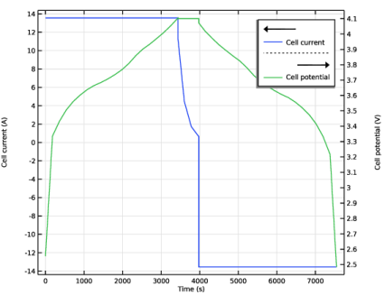
Select the Include constant voltage charging checkbox.
12
In the Iupper text field, type I_upper.
13
Locate the Start Mode section. From the Start with list, choose Charge first.
Run the model at this stage, before adding any aging reactions, in order to check that the battery model cycles correctly.
Study 1
Step 2: Time Dependent
1
In the Model Builder window, under Study 1 click Step 2: Time Dependent.
2
In the Settings window for Time Dependent, locate the Study Settings section.
3
In the Output times text field, type range(0,180,10000).
4
In the Model Builder window, click Study 1.
5
In the Settings window for Study, locate the Study Settings section.
6
Clear the Generate default plots checkbox. For this model we are not interested in the default plots.
7
In the Home toolbar, click  Compute. The model should solve in a few seconds.
Results
Using the variables E_cell and I_cell, defined at the Component 1 > Definitions > Variables 1 node, you can create a plot of the first load cycle as follows:
Load cycle
1
In the Results toolbar, click  1D Plot Group.
2
In the Settings window for 1D Plot Group, type Load cycle in the Label text field.
3
Click to expand the Title section. From the Title type list, choose None.
4
Locate the Plot Settings section. Select the Two y-axes checkbox.
Global 1
1
Right-click Load cycle and choose Global.
2
In the Settings window for Global, locate the y-Axis Data section.
3
Filter 1
1
Right-click Global 1 and choose Filter.
The seed model contained a number of definitions for filter variables, defined under the Component 1 > Definitions > Variables 1 node. These variables have either the value 1 or 0, depending on the charging state of the battery. In the postprocessing part of this tutorial we will use these filter variables extensively to filter out different time ranges of the solution data.
2
In the Settings window for Filter, locate the Point Selection section.
3
In the Logical expression for inclusion text field, type first_cycle_filter.
Global 2
1
In the Model Builder window, under Results > Load cycle right-click Global 1 and choose Duplicate.
2
In the Settings window for Global, locate the y-Axis section.
3
Select the Plot on secondary y-axis checkbox.
4
Locate the y-Axis Data section. In the table, enter the following settings:
5
In the Load cycle toolbar, click  Plot.
Note the time for the 1C discharge, ~3570s. This value will be used as reference in the analysis of the 1C discharge capacity loss later when the SEI formation is accounted for.
Lithium-Ion Battery (liion)
Now return to the battery model and add the needed features for defining the SEI formation reaction. Use the Dissolving-Depositing species functionality to define the SEI layer thickness on the negative electrode.
Porous Electrode 1
1
In the Model Builder window, under Component 1 (comp1) > Lithium-Ion Battery (liion) click Porous Electrode 1.
2
In the Settings window for Porous Electrode, click to expand the Dissolving–Depositing Species section.
3
4
You can control if the volume change induced by a dissolving of depositing species should affect the electrolyte and/or electrode volume fractions. In this case we will assume the formed SEI reduces the electrolyte volume fraction only.
5
Clear the Add volume change to electrode volume fraction checkbox.
Also add a film resistance that depends on the deposited film thickness.
6
Click to expand the Film Resistance section. From the Film resistance list, choose Thickness and conductivity.
7
In the s0 text field, type dfilm_0.
8
From the Δs list, choose Total film thickness change (liion/pce1).
9
In the σfilm text field, type kappa_film.
Porous Electrode Reaction 2
Add a second porous electrode reaction on the negative electrode to account for the parasitic lithium/solvent SEI forming reduction reaction, and set the stoichiometric coefficient for the degradation reaction.
1
In the Physics toolbar, click  Attributes and choose Porous Electrode Reaction.
2
In the Settings window for Porous Electrode Reaction, locate the Equilibrium Potential section.
3
From the Eeq list, choose User defined. Locate the Electrode Kinetics section. From the iloc,expr list, choose User defined. In the associated text field, type I_SEI. The I_SEI variable was already defined in the seed file. You find the definition on the Component 1 > Definitions > Variables 1 node.
4
Locate the Stoichiometric Coefficients section. In the νLiθ text field, type -(t_factor-1). The t_factor parameter is used to speed up the capacity fade per simulated cycle. You can read more about how the parameter is defined in the model documentation above.
5
In the Stoichiometric coefficients for dissolving–depositing species: table, enter the following settings:
6
Click to expand the Heat of Reaction section. From the list, choose User defined. This is just a cosmetic setting to avoid the Materials node reporting missing material properties. The Heat of Reaction settings are not used in the model.
Definitions
Also add a domain integration operator with the default name intop1. It will be used during postprocessing to integrate the amount of cyclable lithium in the battery in order to calculate the remaining capacity.
Integration 1 (intop1)
1
In the Definitions toolbar, click  Nonlocal Couplings and choose Integration.
2
In the Settings window for Integration, locate the Source Selection section.
3
From the Selection list, choose Negative Electrode.
Study 1
The physics part of the model is now complete. Tweak the solver settings before computing.
Step 1: Current Distribution Initialization
Disable the aging reaction in the initialization study step.
1
In the Model Builder window, under Study 1 click Step 1: Current Distribution Initialization.
2
In the Settings window for Current Distribution Initialization, locate the Physics and Variables Selection section.
3
Select the Modify model configuration for study step checkbox.
4
In the tree, select Component 1 (comp1) > Lithium-Ion Battery (liion) > Porous Electrode 1 > Porous Electrode Reaction 2.
5
Step 2: Time Dependent
1
In the Model Builder window, click Step 2: Time Dependent.
2
In the Settings window for Time Dependent, locate the Study Settings section.
3
In the Output times text field, type range(0,180,t_cycling).
Solution 1 (sol1)
1
In the Model Builder window, expand the Study 1 > Solver Configurations node.
Add a stop condition that makes use of a cycle number variable comp1.cycle_no defined at the Component 1 > Definitions > Variables 1 node. This variable in turn is based on an internal variable defined by the Charge-Discharge Cycling node.
2
In the Model Builder window, expand the Solution 1 (sol1) node.
3
Right-click Time-Dependent Solver 1 and choose Stop Condition.
4
In the Settings window for Stop Condition, locate the Stop Expressions section.
5
6
7
Locate the Output at Stop section. From the Add solution list, choose Steps before and after stop.
By enabling storing the solution before and after events, the solution data for the first and last time step of the constant charge current, constant voltage and constant discharge current stages will be stored.
8
Clear the Add information checkbox.
9
In the Model Builder window, click Fully Coupled 1.
10
In the Settings window for Fully Coupled, click to expand the Method and Termination section.
Change the nonlinear method to use a constant damping factor and a minimal jacobian update scheme. This makes the solver less robust, but faster.
11
From the Nonlinear method list, choose Constant (Newton).
12
In the Damping factor text field, type 0.8.
13
In the Study toolbar, click  Compute. The model should solve in about a minute or so.
Results
The following creates a comparison plot of the constant current discharge curves (Figure 1).
Discharge curve comparison
1
In the Results toolbar, click  1D Plot Group.
2
In the Settings window for 1D Plot Group, type Discharge curve comparison in the Label text field.
3
Locate the Title section. From the Title type list, choose Manual.
4
In the Title text area, type Color Legend: Number of cycles.
5
Locate the Plot Settings section.
6
Select the y-axis label checkbox. In the associated text field, type Cell potential (V).
Global 1
1
Right-click Discharge curve comparison and choose Global.
2
In the Settings window for Global, locate the y-Axis Data section.
3
4
Locate the x-Axis Data section. From the Parameter list, choose Expression.
5
In the Expression text field, type (t-liion.cdc1.t_dch_start).
The Charge-Discharge Cycling node stores the latest time for switching to discharge mode in the liion.cdc1.t_dch_start variable. The above expression hence defines the time elapsed since the discharge started within each cycle.
Filter 1
1
Right-click Global 1 and choose Filter.
2
In the Settings window for Filter, locate the Point Selection section.
3
In the Logical expression for inclusion text field, type dch_filter.
4
Locate the Line Segment Selection section. Clear the Decreasing x checkbox.
Color Expression 1
1
In the Model Builder window, right-click Global 1 and choose Color Expression.
2
In the Settings window for Color Expression, locate the Expression section.
3
In the Expression text field, type cycle_no.
4
In the Discharge curve comparison toolbar, click  Plot.
SEI layer potential drop at 1C
The following creates a plot of the potential drop over the SEI layer, using the liion.deltaphi variable defined by the Film Resistance section of the Porous Electrode 1 node (Figure 5).
1
In the Results toolbar, click  1D Plot Group.
2
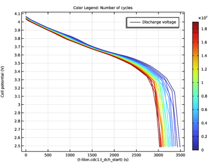
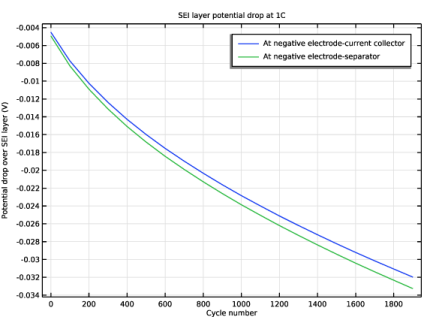
In the Settings window for 1D Plot Group, type SEI layer potential drop at 1C in the Label text field.
3
Locate the Title section. From the Title type list, choose Label.
4
Locate the Plot Settings section.
5
Select the y-axis label checkbox. In the associated text field, type Potential drop over SEI layer (V).
Point Graph 1
1
Right-click SEI layer potential drop at 1C and choose Point Graph.
2
3
In the Settings window for Point Graph, locate the y-Axis Data section.
4
In the Expression text field, type -liion.deltaphi.
5
Locate the x-Axis Data section. From the Parameter list, choose Expression.
6
In the Expression text field, type cycle_no.
7
Select the Description checkbox. In the associated text field, type Cycle number.
8
Click to expand the Legends section. Select the Show legends checkbox.
9
From the Legends list, choose Manual.
10
Filter 1
1
Right-click Point Graph 1 and choose Filter.
2
In the Settings window for Filter, locate the Point Selection section.
3
In the Logical expression for inclusion text field, type dch_start_filter.
Point Graph 2
1
In the Model Builder window, under Results > SEI layer potential drop at 1C right-click Point Graph 1 and choose Duplicate.
2
In the Settings window for Point Graph, locate the Selection section.
3
Click  Clear Selection.
4
5
Locate the Legends section. In the table, enter the following settings:
6
In the SEI layer potential drop at 1C toolbar, click  Plot.
Electrolyte volume fraction
1
In the Model Builder window, right-click SEI layer potential drop at 1C and choose Duplicate.
The electrolyte volume fraction will decrease as a result of the formed SEI. Plot the volume fraction (Figure 4) as follows:
2
In the Settings window for 1D Plot Group, type Electrolyte volume fraction in the Label text field.
3
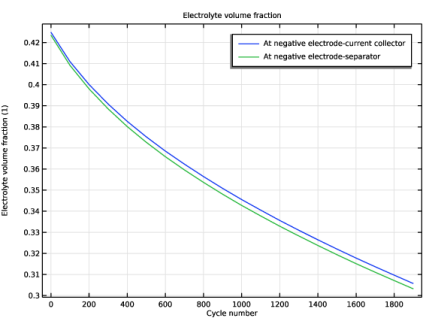
Locate the Plot Settings section. In the y-axis label text field, type Electrolyte volume fraction (1).
Point Graph 1
1
In the Model Builder window, expand the Electrolyte volume fraction node, then click Point Graph 1.
2
In the Settings window for Point Graph, locate the y-Axis Data section.
3
In the Expression text field, type liion.epsl.
Point Graph 2
1
In the Model Builder window, click Point Graph 2.
2
In the Settings window for Point Graph, locate the y-Axis Data section.
3
In the Expression text field, type down(liion.epsl).
The down() operator indicates in this case that the value on the electrode side of the point should be used, not the default mean of the values on each side.
4
In the Electrolyte volume fraction toolbar, click  Plot.
Capacity vs. time
Now plot the capacity versus time (Figure 2). We will compute the remaining capacity in two ways: 1) based on the cyclable charge between 0% and 100% SOC and 2) based on the time elapsed during the 1C discharge.
1
In the Results toolbar, click  1D Plot Group.
2
In the Settings window for 1D Plot Group, type Capacity vs. time in the Label text field.
3
Locate the Title section. From the Title type list, choose None.
4
Locate the Plot Settings section.
5
Select the x-axis label checkbox. In the associated text field, type Time (days) (d).
6
Select the y-axis label checkbox. In the associated text field, type Relative capacity (1).
Global 1
1
Right-click Capacity vs. time and choose Global.
An internal state-of-health (SOH) variable, based on the cyclable lithium, is computed automatically by the SOC and Initial Charge Distribution node.
2
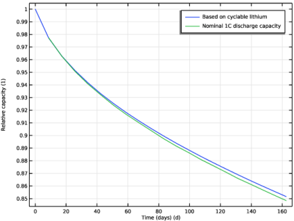
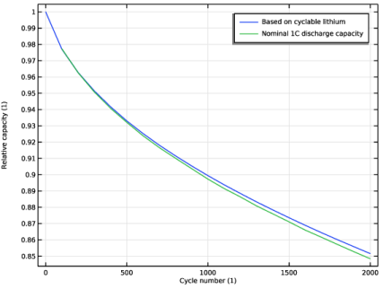
In the Settings window for Global, click Replace Expression in the upper-right corner of the y-Axis Data section. From the menu, choose Component 1 (comp1) > Lithium-Ion Battery > liion.SOH_cell - Cell state of health - 1.
3
Locate the x-Axis Data section. From the Parameter list, choose Expression.
4
In the Expression text field, type t*t_factor.
5
Select the Description checkbox.
6
From the Unit list, choose d.
7
In the Description text field, type Time (days).
8
Click to expand the Legends section. From the Legends list, choose Manual.
9
Filter 1
1
Right-click Global 1 and choose Filter.
2
In the Settings window for Filter, locate the Point Selection section.
3
In the Logical expression for inclusion text field, type ch_start_filter.
Global 2
1
In the Model Builder window, under Results > Capacity vs. time right-click Global 1 and choose Duplicate.
To compute a state-of-health variable based on the 1C discharge capacity, we divide the 1C discharge time for each cycle by the discharge time for the first cycle (which can be deduced by inspecting the Discharge curve comparison plot).
2
In the Settings window for Global, locate the y-Axis Data section.
3
4
Locate the Legends section. In the table, enter the following settings:
Filter 1
1
In the Model Builder window, expand the Global 2 node, then click Filter 1.
2
In the Settings window for Filter, locate the Point Selection section.
3
In the Logical expression for inclusion text field, type ch_start_filter_cycled_once.
Capacity vs. time
1
In the Model Builder window, under Results click Capacity vs. time.
2
In the Capacity vs. time toolbar, click  Plot.
Capacity vs. cycle number
You may also plot the capacity fade versus the cycle number (Figure 3) as follows:
1
Right-click Capacity vs. time and choose Duplicate.
2
In the Settings window for 1D Plot Group, type Capacity vs. cycle number in the Label text field.
3
Locate the Plot Settings section. In the x-axis label text field, type Cycle number (1).
Global 1
1
In the Model Builder window, expand the Capacity vs. cycle number node, then click Global 1.
2
In the Settings window for Global, locate the x-Axis Data section.
3
In the Expression text field, type cycle_no.
Global 2
1
In the Model Builder window, click Global 2.
2
In the Settings window for Global, locate the x-Axis Data section.
3
In the Expression text field, type cycle_no.
4
In the Capacity vs. cycle number toolbar, click  Plot.
Filter 1
1
In the Model Builder window, expand the Global 2 node, then click Filter 1.
2
In the Settings window for Filter, locate the Point Selection section.
3
In the Logical expression for inclusion text field, type ch_start_filter_cycled_once.
Local state of charge at separator-electrode interface
Now plot the local state of charge in electrodes during the first and last cycles (Figure 6).
1
In the Results toolbar, click  1D Plot Group.
2
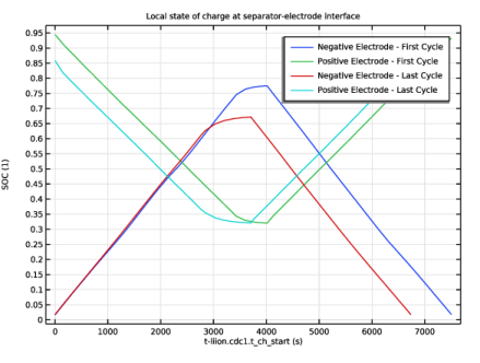
In the Settings window for 1D Plot Group, type Local state of charge at separator-electrode interface in the Label text field.
3
Locate the Title section. From the Title type list, choose Label.
4
Locate the Plot Settings section.
5
Select the y-axis label checkbox. In the associated text field, type SOC (1).
Point Graph 1
1
Right-click Local state of charge at separator-electrode interface and choose Point Graph.
2
3
In the Settings window for Point Graph, locate the y-Axis Data section.
4
In the Expression text field, type liion.socloc_surface.
5
Click to expand the Title section. Locate the x-Axis Data section. From the Parameter list, choose Expression.
6
In the Expression text field, type t-liion.cdc1.t_ch_start.
7
Locate the Legends section. Select the Show legends checkbox.
8
From the Legends list, choose Manual.
9
Filter 1
1
Right-click Point Graph 1 and choose Filter.
2
In the Settings window for Filter, locate the Point Selection section.
3
In the Logical expression for inclusion text field, type first_cycle_filter.
Point Graph 2
1
In the Model Builder window, under Results > Local state of charge at separator-electrode interface right-click Point Graph 1 and choose Duplicate.
2
In the Settings window for Point Graph, locate the Selection section.
3
Click  Clear Selection.
4
5
Locate the Legends section. In the table, enter the following settings:
Point Graph 3
1
Right-click Point Graph 1 and choose Duplicate.
2
In the Settings window for Point Graph, locate the Legends section.
3
Filter 1
1
In the Model Builder window, expand the Point Graph 3 node, then click Filter 1.
2
In the Settings window for Filter, locate the Point Selection section.
3
In the Logical expression for inclusion text field, type last_cycle_filter.
Point Graph 4
1
In the Model Builder window, under Results > Local state of charge at separator-electrode interface right-click Point Graph 2 and choose Duplicate.
2
In the Settings window for Point Graph, locate the Legends section.
3
Filter 1
1
In the Model Builder window, expand the Point Graph 4 node, then click Filter 1.
2
In the Settings window for Filter, locate the Point Selection section.
3
In the Logical expression for inclusion text field, type last_cycle_filter.
4
In the Local state of charge at separator-electrode interface toolbar, click  Plot.