|
|
|
|
•
|
|
•
|
|
1
|
|
2
|
In the Select Physics tree, select Electrochemistry > Batteries > Battery with Binary Electrolyte (batbe).
|
|
3
|
Click Add.
|
|
4
|
Click
|
|
5
|
In the Select Study tree, select Preset Studies for Selected Physics Interfaces > Time Dependent with Initialization.
|
|
6
|
Click
|
|
1
|
|
2
|
|
3
|
|
4
|
Browse to the model’s Application Libraries folder and double-click the file nicd_battery_1d_general.txt.
|
|
1
|
|
2
|
|
3
|
|
4
|
Browse to the model’s Application Libraries folder and double-click the file nicd_battery_1d_cd_electrode.txt.
|
|
1
|
|
2
|
|
3
|
|
4
|
Browse to the model’s Application Libraries folder and double-click the file nicd_battery_1d_ni_electrode.txt.
|
|
1
|
|
2
|
|
3
|
|
4
|
Browse to the model’s Application Libraries folder and double-click the file nicd_battery_1d_electrode_reactions.txt.
|
|
1
|
|
2
|
|
3
|
Locate the Parameters section. In the table, enter the following settings:
|
|
4
|
|
5
|
|
6
|
|
7
|
Click OK.
|
|
8
|
|
9
|
|
10
|
Locate the Parameters section. In the table, enter the following settings:
|
|
1
|
|
2
|
|
3
|
Locate the Parameters section. In the table, enter the following settings:
|
|
4
|
|
5
|
|
7
|
|
8
|
|
10
|
|
11
|
|
13
|
|
14
|
|
15
|
|
16
|
Click OK.
|
|
1
|
In the Model Builder window, expand the Global Definitions > Extra Dimension 1 (xdim1) > Definitions node, then click Global Definitions > Extra Dimension 1 (xdim1).
|
|
2
|
In the Settings window for Extra Dimension, type Extra Dimension: Positive Electrode in the Label text field.
|
|
3
|
Locate the Frames section. Find the Spatial frame coordinates subsection. In the table, enter the following settings:
|
|
1
|
In the Model Builder window, under Global Definitions > Extra Dimension: Positive Electrode (xdim1) right-click Geometry 2 and choose Interval.
|
|
2
|
|
3
|
|
4
|
|
6
|
Click
|
|
1
|
In the Model Builder window, under Global Definitions > Extra Dimension: Positive Electrode (xdim1) right-click Definitions and choose Extra Dimensions > Integration over Extra Dimension.
|
|
2
|
In the Settings window for Integration over Extra Dimension, type Extra Dimension Surface Integral in the Label text field.
|
|
3
|
|
4
|
|
6
|
|
1
|
In the Model Builder window, right-click Extra Dimensions and choose Integration over Extra Dimension.
|
|
2
|
In the Settings window for Integration over Extra Dimension, type Extra Dimension Domain Integral in the Label text field.
|
|
3
|
|
5
|
|
1
|
In the Model Builder window, under Global Definitions > Extra Dimension: Positive Electrode (xdim1) click Mesh 2.
|
|
2
|
|
3
|
From the list, choose User-controlled mesh.
|
|
1
|
Right-click Global Definitions > Extra Dimension: Positive Electrode (xdim1) > Mesh 2 and choose Distribution.
|
|
3
|
|
4
|
|
5
|
|
6
|
|
7
|
Click
|
|
1
|
|
2
|
|
3
|
|
5
|
Click
|
|
1
|
In the Model Builder window, under Component 1 (comp1) right-click Definitions and choose Extra Dimensions > Attached Dimensions.
|
|
2
|
|
3
|
|
5
|
|
6
|
In the Add dialog, select Extra Dimension: Positive Electrode (xdim1) in the Extra dimensions to attach list.
|
|
7
|
Click OK.
|
|
1
|
|
2
|
|
3
|
|
5
|
Locate the Variables section. In the table, enter the following settings:
|
|
1
|
|
2
|
In the Settings window for Variables, type Positive Electrode (Intraparticle) in the Label text field.
|
|
3
|
|
5
|
|
6
|
Locate the Variables section. In the table, enter the following settings:
|
|
1
|
|
2
|
In the Settings window for Variables, type Positive Electrode (Particle Surface) in the Label text field.
|
|
3
|
|
5
|
Locate the Variables section. In the table, enter the following settings:
|
|
1
|
|
2
|
In the Settings window for Integration, type Integration Operator for Positive Electrode Current Collector in the Label text field.
|
|
3
|
|
4
|
|
1
|
|
2
|
In the Settings window for Average, type Positive Electrode Average Operator in the Label text field.
|
|
3
|
|
1
|
|
2
|
In the Settings window for Average, type Negative Electrode Average Operator in the Label text field.
|
|
3
|
|
1
|
|
2
|
Go to the Add Material window.
|
|
3
|
|
4
|
Click the Add to Component button in the window toolbar.
|
|
5
|
|
1
|
In the Model Builder window, expand the Component 1 (comp1) > Battery with Binary Electrolyte (batbe) node, then click Separator 1.
|
|
2
|
|
3
|
|
1
|
|
2
|
|
3
|
|
1
|
|
2
|
In the Settings window for Porous Electrode, type Porous Electrode: Ni (Positive) in the Label text field.
|
|
4
|
|
5
|
|
6
|
|
7
|
|
8
|
Locate the Effective Transport Parameter Correction section. From the Electric conductivity list, choose No correction.
|
|
1
|
In the Model Builder window, under Component 1 (comp1) > Battery with Binary Electrolyte (batbe) > Porous Electrode: Ni (Positive) click Porous Electrode Reaction 1.
|
|
2
|
In the Settings window for Porous Electrode Reaction, type Porous Electrode Reaction: NiOOH + H2O + e- <=> Ni(OH)2 + OH- in the Label text field.
|
|
3
|
|
4
|
|
5
|
|
6
|
|
7
|
Locate the Electrode Kinetics section. From the Kinetics expression type list, choose Butler–Volmer.
|
|
8
|
|
9
|
|
10
|
|
11
|
Locate the Active Specific Surface Area section. From the Active specific surface area list, choose User defined. In the av text field, type a_Ni.
|
|
12
|
|
1
|
|
2
|
In the Settings window for Porous Electrode Reaction, type Porous Electrode Reaction: 1/2 O2 + H2O + 2e- <=> 2 OH- in the Label text field.
|
|
3
|
|
4
|
|
5
|
|
6
|
|
7
|
Locate the Electrode Kinetics section. From the Kinetics expression type list, choose Butler–Volmer.
|
|
8
|
|
9
|
|
10
|
|
11
|
Locate the Active Specific Surface Area section. From the Active specific surface area list, choose User defined. In the av text field, type a_Ni.
|
|
12
|
|
13
|
|
1
|
|
2
|
|
3
|
|
4
|
Click OK.
|
|
1
|
|
2
|
In the Settings window for Weak Contribution, type H+ Diffusion Inside Positive Electrode in the Label text field.
|
|
4
|
Locate the Domain Selection section. From the Extra dimension attachment list, choose Attached Dimensions 1.
|
|
5
|
Click to select the
|
|
7
|
Locate the Weak Contribution section. In the Weak expression text field, type 2*pi*rxd*(particle_diffusive_flux*test(cHrxd)-cHt*test(cH)).
|
|
1
|
|
2
|
In the Settings window for Auxiliary Dependent Variable, type Intraparticle H+ Concentration in the Label text field.
|
|
3
|
Locate the Domain Selection section. From the Extra dimension attachment list, choose Attached Dimensions 1.
|
|
4
|
Click to select the
|
|
6
|
|
7
|
|
1
|
|
2
|
In the Settings window for Weak Contribution, type Boundary Condition for Concentration at Particle Outer Surface in the Label text field.
|
|
4
|
Locate the Domain Selection section. From the Extra dimension attachment list, choose Attached Dimensions 1.
|
|
5
|
|
7
|
Locate the Weak Contribution section. In the Weak expression text field, type -2*batbe.pce1.per1.iloc*test(cH)*pi*rxd/(1[m]*F_const).
|
|
1
|
In the Model Builder window, under Component 1 (comp1) > Battery with Binary Electrolyte (batbe), Ctrl-click to select H+ Diffusion Inside Positive Electrode and Boundary Condition for Concentration at Particle Outer Surface.
|
|
2
|
Right-click and choose Group.
|
|
1
|
|
2
|
|
3
|
Click OK.
|
|
1
|
|
2
|
In the Settings window for Porous Electrode, type Porous Electrode: Cd (Negative) in the Label text field.
|
|
4
|
Locate the Electrode Properties section. From the σs list, choose User defined. In the associated text field, type sigma_electrode.
|
|
5
|
|
6
|
|
7
|
|
8
|
Locate the Effective Transport Parameter Correction section. From the Electric conductivity list, choose No correction.
|
|
9
|
|
11
|
Click
|
|
1
|
In the Model Builder window, under Component 1 (comp1) > Battery with Binary Electrolyte (batbe) > Porous Electrode: Cd (Negative) click Porous Electrode Reaction 1.
|
|
2
|
In the Settings window for Porous Electrode Reaction, type Porous Electrode Reaction: Cd + 2 OH- <=> Cd(OH)2 + 2e- in the Label text field.
|
|
3
|
|
4
|
|
5
|
Locate the Electrode Kinetics section. From the Kinetics expression type list, choose Butler–Volmer.
|
|
6
|
|
7
|
|
8
|
|
9
|
Locate the Active Specific Surface Area section. From the Active specific surface area list, choose User defined. In the av text field, type a_Cd.
|
|
10
|
|
11
|
In the Stoichiometric coefficients for dissolving–depositing species: table, enter the following settings:
|
|
12
|
|
1
|
|
2
|
In the Settings window for Internal Electrode Surface, type Oxygen Recombination at Cd Electrode in the Label text field.
|
|
1
|
In the Model Builder window, under Component 1 (comp1) > Battery with Binary Electrolyte (batbe) > Oxygen Recombination at Cd Electrode click Electrode Reaction 1.
|
|
2
|
In the Settings window for Electrode Reaction, type Electrode Reaction: 1/2 O2 + H2O + 2e- <=> 2 OH- in the Label text field.
|
|
3
|
Locate the Equilibrium Potential section. From the Eeq list, choose User defined. Locate the Electrode Kinetics section. From the iloc,expr list, choose User defined. In the associated text field, type tds.tflux_c_O2x*4*F_const.
|
|
4
|
|
1
|
|
1
|
|
3
|
|
4
|
From the list, choose Average current density.
|
|
5
|
|
1
|
|
2
|
Go to the Add Physics window.
|
|
3
|
|
4
|
Click the Add to Component 1 button in the window toolbar.
|
|
5
|
|
1
|
|
2
|
Clear the Convection checkbox.
|
|
3
|
Select the Mass transfer in porous media checkbox.
|
|
4
|
Click to expand the Dependent Variables section. In the Concentrations (mol/m³) table, enter the following settings:
|
|
1
|
In the Model Builder window, under Component 1 (comp1) > Transport of Diluted Species (tds) click Fluid 1.
|
|
2
|
|
3
|
|
1
|
|
2
|
|
3
|
|
1
|
|
2
|
In the Settings window for Porous Electrode Coupling, type Porous Electrode Coupling: Positive Electrode in the Label text field.
|
|
1
|
|
2
|
|
3
|
From the iv list, choose Local current source, Porous Electrode Reaction: 1/2 O2 + H2O + 2e- <=> 2 OH- (batbe/pce1/per2).
|
|
4
|
|
5
|
|
1
|
|
2
|
In the Settings window for Concentration, type Oxygen Recombination at Cd Electrode in the Label text field.
|
|
4
|
|
1
|
|
3
|
|
4
|
|
1
|
|
2
|
|
1
|
|
2
|
|
3
|
|
4
|
Click
|
|
6
|
Click
|
|
1
|
|
2
|
In the Settings window for Current Distribution Initialization, type Current Distribution Initialization: Primary in the Label text field.
|
|
1
|
In the Study toolbar, click
|
|
2
|
Right-click Discharge and Charge > Step 3: Current Distribution Initialization 2 and choose Move Up.
|
|
3
|
In the Settings window for Current Distribution Initialization, type Current Distribution Initialization: Secondary in the Label text field.
|
|
4
|
|
1
|
|
2
|
|
3
|
|
4
|
|
1
|
|
2
|
|
3
|
In the Model Builder window, expand the Discharge and Charge > Solver Configurations > Solution 1 (sol1) > Dependent Variables 3 node, then click Concentration (comp1.c_O2).
|
|
4
|
|
5
|
|
6
|
|
7
|
In the Model Builder window, under Discharge and Charge > Solver Configurations > Solution 1 (sol1) > Dependent Variables 3 click Auxiliary Dependent Variable CH (comp1.cH).
|
|
8
|
|
9
|
|
10
|
|
11
|
In the Model Builder window, under Discharge and Charge > Solver Configurations > Solution 1 (sol1) right-click Time-Dependent Solver 1 and choose Stop Condition.
|
|
12
|
|
13
|
Click
|
|
15
|
Click
|
|
17
|
|
18
|
|
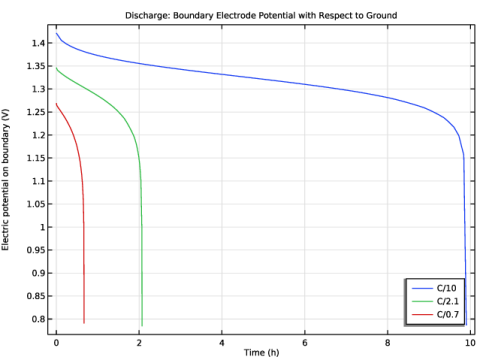
1
|
In the Settings window for 1D Plot Group, type Discharge: Boundary Electrode Potential with Respect to Ground in the Label text field.
|
|
2
|
Locate the Data section. From the Parameter selection (c_H_init, epsilon_3_init, sign, C_rate) list, choose From list.
|
|
3
|
In the Parameter values list, choose 1: c_H_init=104.2, epsilon_3_init=0.6365, sign=-1, C_rate=0.1, 2: c_H_init=104.2, epsilon_3_init=0.6365, sign=-1, C_rate=0.47619, and 3: c_H_init=104.2, epsilon_3_init=0.6365, sign=-1, C_rate=1.4286.
|
|
4
|
|
5
|
|
6
|
|
1
|
In the Model Builder window, expand the Discharge: Boundary Electrode Potential with Respect to Ground node, then click Global 1.
|
|
2
|
|
3
|
|
4
|
|
5
|
|
6
|
|
7
|
|
8
|
|
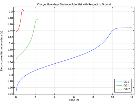
1
|
In the Model Builder window, right-click Discharge: Boundary Electrode Potential with Respect to Ground and choose Duplicate.
|
|
2
|
In the Settings window for 1D Plot Group, type Charge: Boundary Electrode Potential with Respect to Ground in the Label text field.
|
|
3
|
Locate the Data section. In the Parameter values list, choose 4: c_H_init=51994, epsilon_3_init=0.46587, sign=1, C_rate=0.1, 5: c_H_init=51994, epsilon_3_init=0.46587, sign=1, C_rate=0.47619, and 6: c_H_init=51994, epsilon_3_init=0.46587, sign=1, C_rate=1.4286.
|
|
4
|
|
1
|
|
2
|
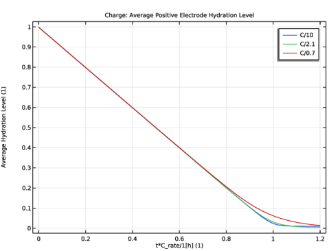
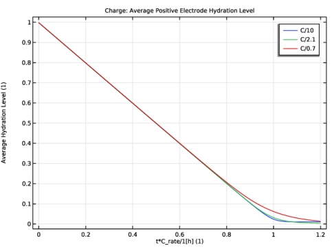
In the Settings window for 1D Plot Group, type Charge: Average Positive Electrode Hydration Level in the Label text field.
|
|
3
|
Locate the Data section. From the Dataset list, choose Discharge and Charge/Parametric Solutions 1 (sol4).
|
|
4
|
|
5
|
In the Parameter values list, choose 4: c_H_init=51994, epsilon_3_init=0.46587, sign=1, C_rate=0.1, 5: c_H_init=51994, epsilon_3_init=0.46587, sign=1, C_rate=0.47619, and 6: c_H_init=51994, epsilon_3_init=0.46587, sign=1, C_rate=1.4286.
|
|
6
|
|
1
|
|
2
|
|
4
|
|
5
|
|
6
|
|
7
|
|
8
|
|
1
|
|
2
|
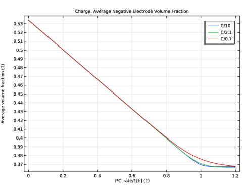
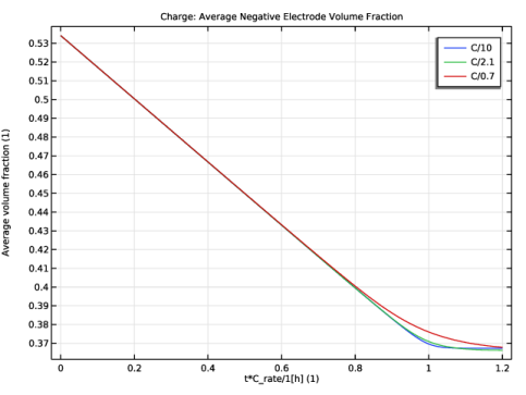
In the Settings window for 1D Plot Group, type Charge: Average Negative Electrode Volume Fraction in the Label text field.
|
|
3
|
Locate the Data section. From the Dataset list, choose Discharge and Charge/Parametric Solutions 1 (sol4).
|
|
4
|
|
5
|
In the Parameter values list, choose 4: c_H_init=51994, epsilon_3_init=0.46587, sign=1, C_rate=0.1, 5: c_H_init=51994, epsilon_3_init=0.46587, sign=1, C_rate=0.47619, and 6: c_H_init=51994, epsilon_3_init=0.46587, sign=1, C_rate=1.4286.
|
|
6
|
|
1
|
|
2
|
|
4
|
|
5
|
|
6
|
|
7
|
|
8
|