
PDF

Lithium Plating with Deformation
Introduction
In a lithium metal battery, lithium metal is deposited during charging on the negative electrode according to
Due to mass transport and ohmic effects in the electrolyte, small initial protrusions on the metal surface will be subjected to accelerated growth during charging, which in the worst case may lead to the formation of dendrites, subsequent internal short circuits, and thermal runaway. This example explores the method of reverse pulse charging for mitigating the formation of dendrites.
The model uses the Lithium-Ion Battery, Deformed Geometry model wizard entry that adds a Lithium-Ion Battery interface along with Deformed Geometry formulation.
Model Definition
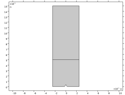
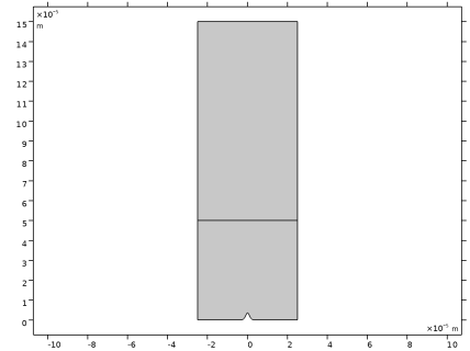
Figure 1 shows the model geometry of the lithium-ion battery that consists of two domains (positive porous electrode and separator). The negative lithium metal electrode surface is located at y = 0 mm, with a small protrusion with a height of 40 mm, centered around x = 0. The materials considered are NMC 622 and LiPF6 3:7 EC:EMC for the positive electrode and electrolyte, respectively.
Figure 1: Model geometry.
In the first part of the tutorial, a forward current plating model is set up to simulate how a small protrusion of lithium grows during the plating process. A constant electrode current density of 1C is applied on the top boundary of the positive porous electrode, and the resulting growth velocity along the negative lithium electrode surface is used as a boundary condition for the deformed geometry (ALE) time-dependent simulation.
In the second part of the tutorial, a forward and reverse current duty cycle is set up to examine how the protrusion of lithium is attenuated depending on the length of the reverse pulse. The current density for the reverse pulse irev on the top boundary of the positive porous electrode is set to 15C. Denoting the forward duty cycle (the relative time spent in forward mode) as tfwd (dimensionless) and the overall current density as iavg, the forward pulse current density ifwd can be calculated as
(1)
The total simulated plating time is 0.75 h. The cycle time for a single forward and reverse duty cycle is 180 s. The Load Cycle boundary node is used to set up the switching between the forward and reverse current duty cycles. The applied C rate on the top boundary of the positive porous electrode is appropriately calculated based on the forward and reverse states and respective rates. A parametric sweep is set up in the second part of the tutorial to simulate different lengths of the forward plating duty cycle tfwd and examine the lithium electrode surface evolution during the forward and reverse current duty cycle.
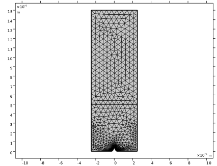
This model uses linear elements for all the dependent variables in the Lithium-Ion Battery interface for faster computation times.
Results and Discussion
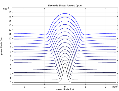
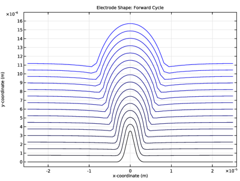
Figure 2 shows the lithium electrode surface profile evolution during the forward plating cycle. The initial protrusion grows in size and will result in an uneven surface.
Figure 2: Electrode shape evolution for forward current duty cycle (tfwd = 1).
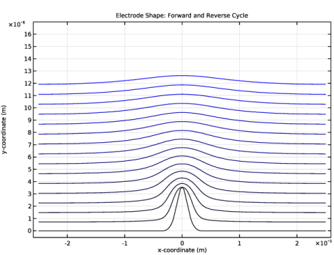
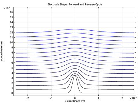
Figure 3 shows the lithium electrode surface profile evolution during the forward and reverse current duty cycle, for tfwd = 0.9. The initial protrusion is now attenuated as the plating proceeds.
Figure 3: Electrode shape evolution for forward and reverse current duty cycle (tfwd = 0.9).
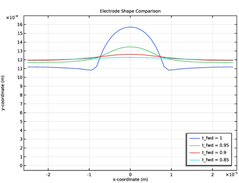
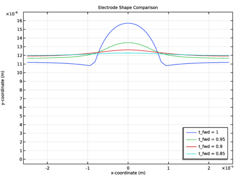
Figure 4: Comparison of final electrode surface profiles for different values of tfwd.
Finally, Figure 4 shows a comparison of the lithium electrode surface profiles at the last time step for different values of the forward plating duty cycle tfwd.
Application Library path: Battery_Design_Module/Lithium-Ion_Batteries,_Aging_and_Abuse/li_plating_with_deformation
Modeling Instructions
This tutorial consists of two parts. In the first part you will set up a forward current plating model to simulate how a small protrusion of lithium grows during the plating process.
In the second part you will set up a forward and reverse current duty cycle, and examine how the protrusion of lithium is attenuated depending on the length of the reverse pulse.
From the File menu, choose New.
New
In the New window, click  Model Wizard.
Model Wizard
1
In the Model Wizard window, click  2D.
2
In the Select Physics tree, select Electrochemistry > Batteries > Lithium-Ion Battery, Deformed Geometry.
3
Click Add.
4
Click  Study.
5
In the Select Study tree, select Preset Studies for Selected Physics Interfaces > Time Dependent with Initialization.
6
Global Definitions
Parameters 1
Load the model parameters from a text file.
1
In the Model Builder window, under Global Definitions click Parameters 1.
2
In the Settings window for Parameters, locate the Parameters section.
3
Click  Load from File.
4
Geometry 1
Set up the geometry that consists of two domains (positive porous electrode and separator). The negative lithium electrode surface is located at y = 0 mm, with a small protrusion with a height of 40 mm, centered at x = 0.
Polygon 1 (pol1)
1
In the Geometry toolbar, click  Polygon.
2
In the Settings window for Polygon, locate the Coordinates section.
3
Rectangle 1 (r1)
1
In the Geometry toolbar, click  Rectangle.
2
In the Settings window for Rectangle, locate the Size and Shape section.
3
In the Width text field, type W_cell.
4
In the Height text field, type H_pos.
5
Locate the Position section. In the x text field, type -W_cell/2.
6
In the y text field, type H_sep.
Fillet 1 (fil1)
Round the corners by adding fillets.
1
In the Geometry toolbar, click  Fillet.
2
On the object pol1, select Point 1 only.
3
In the Settings window for Fillet, locate the Radius section.
4
In the Radius text field, type H_prot/10.
Fillet 2 (fil2)
1
In the Geometry toolbar, click  Fillet.
2
On the object fil1, select Points 3 and 6 only.
3
In the Settings window for Fillet, locate the Radius section.
4
In the Radius text field, type W_prot/2.
5
In the Geometry toolbar, click  Build All.
6
Click the  Zoom Extents button in the Graphics toolbar.
7
In the Model Builder window, click Geometry 1.
Add Material
The model has a lithium metal negative electrode, a NMC 622 positive electrode, and a LiPF6 3:7 EC:EMC electrolyte. Import the materials from the Battery material library.
1
In the Materials toolbar, click  Add Material to open the Add Material window.
2
Go to the Add Material window.
3
In the tree, select Battery > Electrolytes > LiPF6 in 3:7 EC:EMC (Liquid, Li-ion Battery).
4
Click the Add to Component button in the window toolbar.
Add Material
1
Go to the Add Material window.
2
In the tree, select Battery > Electrodes > NMC 622, LiNi0.6Mn0.2Co0.2O2 (Positive, Li-ion Battery).
3
Click the Add to Component button in the window toolbar.
Add Material
1
Go to the Add Material window.
2
In the tree, select Battery > Electrodes > Lithium Metal, Li (Negative, Li-ion Battery).
3
Click the Add to Component button in the window toolbar.
4
In the Materials toolbar, click  Add Material to close the Add Material window.
Materials
NMC 622, LiNi0.6Mn0.2Co0.2O2 (Positive, Li-ion Battery) (mat2)
1
In the Model Builder window, click NMC 622, LiNi0.6Mn0.2Co0.2O2 (Positive, Li-ion Battery) (mat2).
2
Lithium Metal, Li (Negative, Li-ion Battery) (mat3)
1
In the Model Builder window, click Lithium Metal, Li (Negative, Li-ion Battery) (mat3).
2
In the Settings window for Material, locate the Geometric Entity Selection section.
3
From the Geometric entity level list, choose Boundary.
Use a box selection to select all the (lower) boundaries pertaining to the lithium electrode surface, including the protrusion.
4
5
Click  Create Selection.
By creating a selection in this way you can conveniently select the same set of boundaries again later on.
6
In the Create Selection dialog, type Lithium Electrode Surface in the Selection name text field.
7
Lithium-Ion Battery (liion)
Now start setting up the forward cycle lithium-ion battery model.
Porous Electrode 1
1
In the Physics toolbar, click  Domains and choose Porous Electrode.
2
3
In the Settings window for Porous Electrode, locate the Electrolyte Properties section.
4
From the Electrolyte material list, choose LiPF6 in 3:7 EC:EMC (Liquid, Li-ion Battery) (mat1).
5
Locate the Electrode Properties section. In the σs text field, type sigmas_pos.
6
Locate the Porous Matrix Properties section. In the εs text field, type epss_pos.
Particle Intercalation 1
1
In the Model Builder window, click Particle Intercalation 1.
2
In the Settings window for Particle Intercalation, locate the Particle Transport Properties section.
3
In the rp text field, type rp_pos.
Electrode Surface 1
1
In the Physics toolbar, click  Boundaries and choose Electrode Surface.
2
In the Settings window for Electrode Surface, locate the Boundary Selection section.
3
From the Selection list, choose Lithium Electrode Surface.
Use a Dissolving-Depositing Species to define the growth velocity of the lithium electrode surface.
4
Click to expand the Dissolving–Depositing Species section. Click  Add.
5
6
Clear the Solve for surface concentration variables checkbox.
Electrode Reaction 1
1
In the Model Builder window, click Electrode Reaction 1.
2
In the Settings window for Electrode Reaction, locate the Stoichiometric Coefficients section.
3
In the Stoichiometric coefficients for dissolving–depositing species: table, enter the following settings:
4
In the Model Builder window, click Lithium-Ion Battery (liion).
5
In the Settings window for Lithium-Ion Battery, locate the Cell Settings section.
6
Select the Define cell state of charge (SOC) and initial charge inventory checkbox.
SOC and Initial Charge Distribution 1
1
In the Model Builder window, under Component 1 (comp1) > Lithium-Ion Battery (liion) click SOC and Initial Charge Distribution 1.
2
In the Settings window for SOC and Initial Charge Distribution, locate the Cell Type section.
3
4
Locate the Initial Cell Charge Distribution section. In the SOC0 text field, type 0.
Positive Electrode Domain Selection 1
1
In the Model Builder window, click Positive Electrode Domain Selection 1.
2
Load Cycle: Forward Only
1
In the Physics toolbar, click  Boundaries and choose Load Cycle.
2
In the Settings window for Load Cycle, type Load Cycle: Forward Only in the Label text field.
3
4
Locate the Load Type section. From the list, choose Galvanostatic.
5
Locate the Continuation Conditions section. Select the Use elapsed time only checkbox.
C Rate 1
1
In the Physics toolbar, click  Attributes and choose C Rate.
2
In the Settings window for C Rate, locate the C-Rate Multiple section.
3
In the Cset text field, type C_rate_avg.
Global Definitions
Default Model Inputs
1
In the Model Builder window, under Global Definitions click Default Model Inputs.
2
In the Settings window for Default Model Inputs, locate the Browse Model Inputs section.
3
In the tree, select General > Temperature (K) - minput.T.
4
Find the Expression for remaining selection subsection. In the Temperature text field, type T.
Deformed Geometry
Select the separator domain as the Deforming Domain.
Deforming Domain 1
1
In the Model Builder window, expand the Deformed Geometry node, then click Deforming Domain 1.
2
Multiphysics
Nondeforming Boundary 1 (ndbdg1)
Set zero normal displacement at the vertical nondeforming boundaries.
1
In the Model Builder window, expand the Multiphysics node, then click Nondeforming Boundary 1 (ndbdg1).
2
In the Settings window for Nondeforming Boundary, locate the Nondeforming Boundary section.
3
From the Boundary condition list, choose Zero normal displacement.
Lithium-Ion Battery (liion)
Set linear elements for all the dependent variables in the Lithium-Ion Battery interface to speed up computation time.
1
In the Model Builder window, under Component 1 (comp1) click Lithium-Ion Battery (liion).
2
In the Settings window for Lithium-Ion Battery, click to expand the Discretization section.
3
From the Electrolyte potential list, choose Linear.
4
From the Electrolyte salt concentration list, choose Linear.
5
From the Electric potential list, choose Linear.
Mesh 1
Modify the mesh as follows to get more mesh elements along the lithium electrode surface.
Free Triangular 1
In the Mesh toolbar, click  Free Triangular.
Size 1
1
Right-click Free Triangular 1 and choose Size.
2
In the Settings window for Size, locate the Geometric Entity Selection section.
3
From the Geometric entity level list, choose Boundary.
4
From the Selection list, choose Lithium Electrode Surface.
5
Locate the Element Size section. Click the Custom button.
6
Locate the Element Size Parameters section.
7
Select the Maximum element growth rate checkbox. In the associated text field, type 1.1.
Size
1
In the Model Builder window, under Component 1 (comp1) > Mesh 1 click Size.
2
In the Settings window for Size, locate the Element Size section.
3
From the Predefined list, choose Finer.
4
Click  Build All.
Study: Forward Cycle
The forward cycle problem is now ready for solving. Update the time unit and output times before solving.
1
In the Model Builder window, click Study 1.
2
In the Settings window for Study, type Study: Forward Cycle in the Label text field.
Step 2: Time Dependent
1
In the Model Builder window, expand the Study: Forward Cycle node, then click Step 2: Time Dependent.
2
In the Settings window for Time Dependent, locate the Study Settings section.
3
From the Time unit list, choose h.
4
In the Output times text field, type range(0,0.05/C_rate_avg,0.75/C_rate_avg).
5
In the Study toolbar, click  Compute.
Results
Create a line plot for the shape of the lithium electrode surface at different times during the forward cycle (Figure 2) as follows:
Electrode Shape: Forward Cycle
1
In the Results toolbar, click  1D Plot Group.
2
In the Settings window for 1D Plot Group, type Electrode Shape: Forward Cycle in the Label text field.
3
Click to expand the Title section. From the Title type list, choose Label.
Line Graph 1
1
Right-click Electrode Shape: Forward Cycle and choose Line Graph.
2
In the Settings window for Line Graph, locate the Selection section.
3
From the Selection list, choose Lithium Electrode Surface.
4
Locate the y-Axis Data section. In the Expression text field, type y.
5
Locate the x-Axis Data section. From the Parameter list, choose Expression.
6
In the Expression text field, type x.
7
Click to expand the Coloring and Style section. From the Color list, choose Gradient.
8
From the Top color list, choose Blue.
Electrode Shape: Forward Cycle
1
In the Model Builder window, click Electrode Shape: Forward Cycle.
2
In the Settings window for 1D Plot Group, locate the Axis section.
3
Select the Manual axis limits checkbox.
4
In the y minimum text field, type -5.5e-7.
5
In the y maximum text field, type 1.7e-5.
6
In the Electrode Shape: Forward Cycle toolbar, click  Plot.
Lithium-Ion Battery (liion)
You have now completed the first part of this tutorial where the applied current included only the forward current duty cycle. We will now set up the second part of the tutorial where the applied current includes both the forward and reverse current duty cycles.
Load Cycle: Forward and Reverse
1
In the Model Builder window, right-click Load Cycle: Forward Only and choose Duplicate.
2
In the Settings window for Load Cycle, type Load Cycle: Forward and Reverse in the Label text field.
C Rate 1
1
In the Model Builder window, expand the Load Cycle: Forward and Reverse node, then click C Rate 1.
2
In the Settings window for C Rate, locate the C-Rate Multiple section.
3
In the Cset text field, type C_rate_fwd.
4
Locate the Continuation Conditions section. Select the Elapsed time checkbox.
5
In the tmax text field, type t_fwd*T_cycle.
Load Cycle: Forward and Reverse
In the Model Builder window, click Load Cycle: Forward and Reverse.
C Rate 2
1
In the Physics toolbar, click  Attributes and choose C Rate.
2
In the Settings window for C Rate, locate the C-Rate Multiple section.
3
In the Cset text field, type C_rate_rev.
4
Locate the Continuation Conditions section. Select the Elapsed time checkbox.
5
In the tmax text field, type t_rev*T_cycle.
Add Study
The forward and reverse cycle model is now ready for solving. Use a Parametric Sweep to simulate different lengths of the forward plating duty cycle.
1
In the Home toolbar, click  Add Study to open the Add Study window.
2
Go to the Add Study window.
3
Find the Studies subsection. In the Select Study tree, select Preset Studies for Selected Physics Interfaces > Time Dependent with Initialization.
4
Click the Add Study button in the window toolbar.
5
In the Home toolbar, click  Add Study to close the Add Study window.
Study: Forward and Reverse Cycle
1
In the Model Builder window, click Study 2.
2
In the Settings window for Study, type Study: Forward and Reverse Cycle in the Label text field.
Parametric Sweep
1
In the Study toolbar, click  Parametric Sweep.
2
In the Settings window for Parametric Sweep, locate the Study Settings section.
3
4
Step 1: Current Distribution Initialization
Also, disable Load Cycle: Forward Only node in this study.
1
In the Model Builder window, click Step 1: Current Distribution Initialization.
2
In the Settings window for Current Distribution Initialization, locate the Physics and Variables Selection section.
3
Select the Modify model configuration for study step checkbox.
4
In the tree, select Component 1 (comp1) > Lithium-Ion Battery (liion) > Load Cycle: Forward Only.
5
Click  Disable.
Step 2: Time Dependent
1
In the Model Builder window, click Step 2: Time Dependent.
2
In the Settings window for Time Dependent, locate the Study Settings section.
3
From the Time unit list, choose h.
4
In the Output times text field, type range(0,0.05/C_rate_avg,0.75/C_rate_avg).
5
Locate the Physics and Variables Selection section. Select the Modify model configuration for study step checkbox.
6
In the tree, select Component 1 (comp1) > Lithium-Ion Battery (liion) > Load Cycle: Forward Only.
7
Click  Disable.
8
Click to expand the Study Extensions section. Select the Automatic remeshing checkbox.
Study: Forward Cycle
Before solving the forward and reverse cycle study, disable appropriate nodes in the forward cycle study for completeness.
Step 1: Current Distribution Initialization
1
In the Model Builder window, under Study: Forward Cycle click Step 1: Current Distribution Initialization.
2
In the Settings window for Current Distribution Initialization, locate the Physics and Variables Selection section.
3
Select the Modify model configuration for study step checkbox.
4
In the tree, select Component 1 (comp1) > Lithium-Ion Battery (liion) > Load Cycle: Forward and Reverse.
5
Click  Disable.
Step 2: Time Dependent
1
In the Model Builder window, click Step 2: Time Dependent.
2
In the Settings window for Time Dependent, locate the Physics and Variables Selection section.
3
Select the Modify model configuration for study step checkbox.
4
In the tree, select Component 1 (comp1) > Lithium-Ion Battery (liion) > Load Cycle: Forward and Reverse.
5
Click  Disable.
Study: Forward and Reverse Cycle
Finally, solve the forward and reverse cycle model.
1
In the Model Builder window, click Study: Forward and Reverse Cycle.
2
In the Settings window for Study, locate the Study Settings section.
3
Clear the Generate default plots checkbox.
4
In the Study toolbar, click  Compute.
Results
As before, create a line plot for the shape of the lithium electrode surface at different times during the forward and reverse cycle (Figure 3).
Electrode Shape: Forward and Reverse Cycle
1
In the Model Builder window, right-click Electrode Shape: Forward Cycle and choose Duplicate.
2
In the Settings window for 1D Plot Group, type Electrode Shape: Forward and Reverse Cycle in the Label text field.
3
Locate the Data section. From the Dataset list, choose Study: Forward and Reverse Cycle/Parametric Solutions 1 (sol6).
4
From the Parameter selection (t_fwd) list, choose From list.
5
In the Parameter values (t_fwd) list box, select 0.9.
6
From the Time selection list, choose Interpolated.
7
In the Times (h) text field, type range(0,0.05,0.75).
8
In the Electrode Shape: Forward and Reverse Cycle toolbar, click  Plot.
Electrode Shape Comparison
Finally, create a line plot for the shape of the lithium electrode surface at the last time step for different values of the forward plating duty cycle (Figure 4).
1
In the Results toolbar, click  1D Plot Group.
2
In the Settings window for 1D Plot Group, type Electrode Shape Comparison in the Label text field.
3
Locate the Data section. From the Dataset list, choose None.
4
Click to expand the Title section. From the Title type list, choose Label.
Line Graph 1
1
Right-click Electrode Shape Comparison and choose Line Graph.
2
In the Settings window for Line Graph, locate the Data section.
3
From the Dataset list, choose Study: Forward Cycle/Solution 1 (sol1).
4
From the Time selection list, choose Last.
5
Locate the Selection section. From the Selection list, choose Lithium Electrode Surface.
6
Locate the y-Axis Data section. In the Expression text field, type y.
7
Locate the x-Axis Data section. From the Parameter list, choose Expression.
8
In the Expression text field, type x.
9
Click to expand the Legends section. Select the Show legends checkbox.
10
From the Legends list, choose Evaluated.
11
In the Legend text field, type t_fwd = 1.
Line Graph 2
1
Right-click Line Graph 1 and choose Duplicate.
2
In the Settings window for Line Graph, locate the Data section.
3
From the Dataset list, choose Study: Forward and Reverse Cycle/Parametric Solutions 1 (sol6).
4
From the Time selection list, choose Last.
5
Locate the Legends section. In the Legend text field, type t_fwd = eval(t_fwd).
Electrode Shape Comparison
1
In the Model Builder window, click Electrode Shape Comparison.
2
In the Settings window for 1D Plot Group, locate the Axis section.
3
Select the Manual axis limits checkbox.
4
In the y minimum text field, type -5.5e-7.
5
In the y maximum text field, type 1.7e-5.
6
Locate the Legend section. From the Position list, choose Lower right.
7
In the Electrode Shape Comparison toolbar, click  Plot.