|
|
|
|
1
|
|
2
|
In the Select Physics tree, select Acoustics > Pressure Acoustics > Pressure Acoustics, Boundary Elements (pabe).
|
|
3
|
Click Add.
|
|
4
|
Click
|
|
5
|
|
6
|
Click
|
|
1
|
|
2
|
|
3
|
Click
|
|
4
|
Browse to the model’s Application Libraries folder and double-click the file head_torso_hrtf_parameters.txt.
|
|
1
|
|
2
|
|
3
|
|
4
|
Click
|
|
5
|
Browse to the model’s Application Libraries folder and double-click the file head_torso_hrtf_measured.txt.
|
|
6
|
Locate the Data Column Settings section. In the table, enter the following settings:
|
|
8
|
|
10
|
|
11
|
|
13
|
|
14
|
|
16
|
|
17
|
|
19
|
|
20
|
|
22
|
|
23
|
|
25
|
|
26
|
|
27
|
Locate the Interpolation and Extrapolation section. From the Interpolation list, choose Piecewise cubic.
|
|
28
|
|
29
|
|
1
|
|
2
|
|
3
|
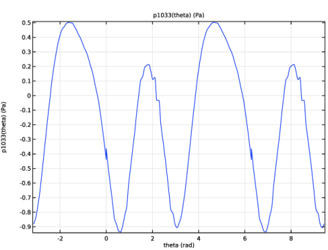
Locate the Definition section. In the Expression text field, type HRTF_1033_real(theta+theta0)+i*HRTF_1033_imag(theta+theta0).
|
|
4
|
|
5
|
|
6
|
|
7
|
Locate the Units section. In the table, enter the following settings:
|
|
8
|
|
9
|
Click to expand the Advanced section. Select the May produce complex output for real arguments checkbox.
|
|
10
|
Locate the Plot Parameters section. In the table, enter the following settings:
|
|
11
|
|
1
|
|
2
|
|
3
|
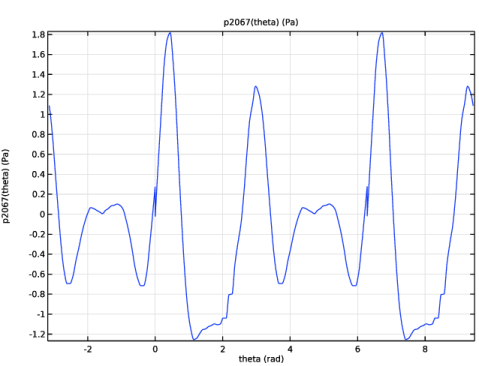
Locate the Definition section. In the Expression text field, type HRTF_2067_real(theta+theta0)+i*HRTF_2067_imag(theta+theta0).
|
|
4
|
|
1
|
|
2
|
|
3
|
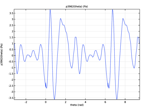
Locate the Definition section. In the Expression text field, type HRTF_3962_real(theta+theta0)+i*HRTF_3962_imag(theta+theta0).
|
|
4
|
|
5
|
|
1
|
|
2
|
Select the Use units checkbox.
|
|
3
|
|
1
|
|
2
|
|
3
|
Click
|
|
4
|
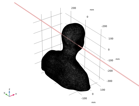
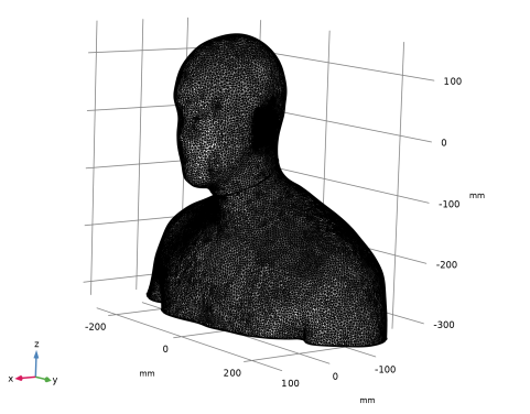
Browse to the model’s Application Libraries folder and double-click the file head_torso_hrtf_scan.stl.
|
|
5
|
|
6
|
|
1
|
|
2
|
|
3
|
|
4
|
|
5
|
Click
|
|
1
|
|
2
|
|
3
|
|
4
|
|
5
|
|
6
|
|
7
|
|
1
|
|
2
|
|
3
|
|
4
|
|
5
|
|
6
|
|
7
|
|
8
|
Click
|
|
1
|
|
1
|
|
2
|
|
3
|
|
4
|
|
5
|
Click
|
|
1
|
|
2
|
|
1
|
|
2
|
|
1
|
|
2
|
Go to the Add Material window.
|
|
3
|
|
4
|
Click the Add to Component button in the window toolbar.
|
|
5
|
|
1
|
|
2
|
|
1
|
In the Model Builder window, under Component 1 (comp1) click Pressure Acoustics, Boundary Elements (pabe).
|
|
2
|
In the Settings window for Pressure Acoustics, Boundary Elements, locate the Domain Selection section.
|
|
3
|
|
1
|
|
3
|
|
4
|
|
1
|
|
2
|
|
3
|
Click the Custom button.
|
|
4
|
Locate the Element Size Parameters section. In the Maximum element size text field, type min(20[mm],lam0/4).
|
|
5
|
|
6
|
|
1
|
|
2
|
|
3
|
|
1
|
|
2
|
|
3
|
Click the Custom button.
|
|
4
|
Locate the Element Size Parameters section.
|
|
5
|
|
6
|
|
7
|
Click
|
|
9
|
|
1
|
|
2
|
|
3
|
|
1
|
|
2
|
|
3
|
|
1
|
|
2
|
|
3
|
Click
|
|
5
|
|
1
|
|
2
|
|
3
|
|
4
|
|
5
|
|
6
|
|
7
|
|
8
|
|
9
|
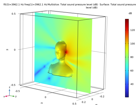
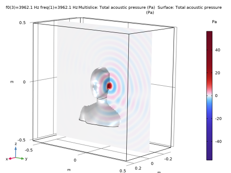
Click to expand the Grid section. Now, set the resolution of the evaluation grid. This resolution should be adequate to resolve the wave pattern being visualized (the wavelength). If the resolution is too poor the results will appear wrong.
|
|
10
|
|
11
|
|
12
|
|
13
|
|
1
|
|
2
|
|
3
|
Click OK.
|
|
1
|
|
2
|
|
3
|
From the View list, choose New view. This allows you to set up and use a dedicated view for this plot group.
|
|
4
|
|
5
|
|
1
|
In the Model Builder window, expand the Results > Views node, then click Results > Acoustic Pressure (pabe).
|
|
2
|
|
3
|
|
1
|
|
2
|
|
3
|
|
4
|
|
5
|
Locate the Coloring and Style section. From the Color table transformation list, choose Nonlinear symmetric.
|
|
6
|
|
7
|
|
1
|
|
2
|
|
3
|
|
1
|
|
2
|
|
3
|
|
4
|
|
5
|
|
1
|
|
2
|
|
3
|
|
4
|
|
1
|
|
2
|
|
3
|
|
4
|
Locate the Evaluation section. Find the Angles subsection. In the Number of angles text field, type 360.
|
|
5
|
Click Preview Evaluation Plane.
|
|
6
|
|
7
|
|
8
|
|
1
|
|
2
|
|
3
|
|
4
|
|
1
|
|
2
|
|
1
|
|
2
|
|
3
|
|
4
|
|
1
|
|
2
|
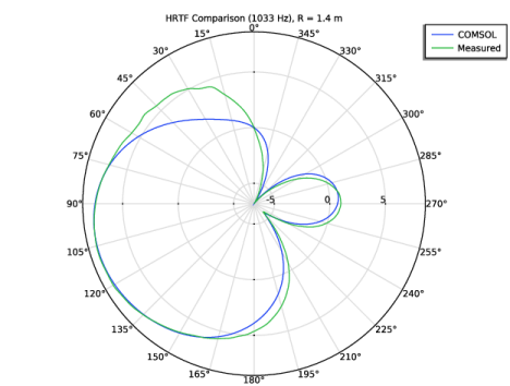
In the Settings window for Polar Plot Group, type HRTF Comparison (1033 Hz), R = 1.4 m in the Label text field.
|
|
3
|
|
4
|
|
5
|
|
6
|
|
7
|
|
1
|
|
2
|
|
3
|
|
4
|
Locate the Evaluation section. Find the Angles subsection. In the Number of angles text field, type 360.
|
|
5
|
|
6
|
|
7
|
|
1
|
|
2
|
|
3
|
|
4
|
Locate the Evaluation section. Find the Angles subsection. In the Number of angles text field, type 360.
|
|
5
|
|
6
|
|
7
|
|
9
|
|
1
|
|
2
|
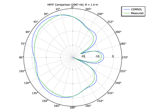
In the Settings window for Polar Plot Group, type HRTF Comparison (2067 Hz), R = 1.4 m in the Label text field.
|
|
3
|
|
1
|
In the Model Builder window, expand the HRTF Comparison (2067 Hz), R = 1.4 m node, then click Radiation Pattern 2.
|
|
2
|
|
3
|
|
4
|
|
1
|
|
2
|
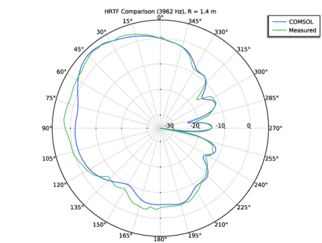
In the Settings window for Polar Plot Group, type HRTF Comparison (3962 Hz), R = 1.4 m in the Label text field.
|
|
3
|
|
1
|
In the Model Builder window, expand the HRTF Comparison (3962 Hz), R = 1.4 m node, then click Radiation Pattern 2.
|
|
2
|
|
3
|
|
4
|