|
|
|

|
1
|
|
2
|
In the Select Physics tree, select Acoustics > Pressure Acoustics > Pressure Acoustics, Frequency Domain (acpr).
|
|
3
|
Click Add.
|
|
4
|
In the Select Physics tree, select Acoustics > Thermoviscous Acoustics > Thermoviscous Acoustics, Frequency Domain (ta).
|
|
5
|
Click Add.
|
|
6
|
Click
|
|
1
|
|
2
|
|
3
|
Click
|
|
4
|
Browse to the model’s Application Libraries folder and double-click the file generic_711_coupler_parameters.txt.
|
|
1
|
|
2
|
|
3
|
|
4
|
Click
|
|
5
|
Browse to the model’s Application Libraries folder and double-click the file generic_711_coupler_transfer_impedance.txt.
|
|
6
|
Click
|
|
7
|
Locate the Data Column Settings section. In the table, enter the following settings:
|
|
8
|
|
10
|
|
12
|
|
1
|
|
2
|
|
3
|
|
4
|
Click
|
|
5
|
Browse to the model’s Application Libraries folder and double-click the file generic_711_coupler_mic_response.txt.
|
|
6
|
Click
|
|
7
|
Locate the Data Column Settings section. In the table, enter the following settings:
|
|
8
|
|
10
|
|
12
|
|
1
|
|
2
|
|
3
|
Click
|
|
4
|
Browse to the model’s Application Libraries folder and double-click the file generic_711_coupler.mphbin.
|
|
5
|
Click
|
|
6
|
|
1
|
|
2
|
|
3
|
Click
|
|
4
|
Browse to the model’s Application Libraries folder and double-click the file generic_711_coupler_variables.txt.
|
|
1
|
|
2
|
|
3
|
|
1
|
|
2
|
|
3
|
|
1
|
|
2
|
|
1
|
|
2
|
|
1
|
|
3
|
|
1
|
|
3
|
|
1
|
|
2
|
|
3
|
|
5
|
|
1
|
|
2
|
Go to the Add Material window.
|
|
3
|
|
4
|
Click the Add to Component button in the window toolbar.
|
|
5
|
|
1
|
In the Settings window for Pressure Acoustics, Frequency Domain, locate the Domain Selection section.
|
|
2
|
|
1
|
In the Model Builder window, under Component 1 (comp1) > Pressure Acoustics, Frequency Domain (acpr) click Pressure Acoustics 1.
|
|
2
|
|
3
|
|
1
|
|
2
|
|
3
|
|
1
|
|
3
|
|
4
|
|
1
|
|
3
|
|
4
|
|
5
|
|
6
|
|
7
|
|
1
|
In the Model Builder window, under Component 1 (comp1) > Thermoviscous Acoustics, Frequency Domain (ta) click Thermoviscous Acoustics Model 1.
|
|
2
|
|
3
|
|
4
|
|
5
|
In the Settings window for Thermoviscous Acoustics, Frequency Domain, locate the Domain Selection section.
|
|
6
|
|
1
|
|
2
|
|
3
|
|
1
|
In the Physics toolbar, click
|
|
2
|
In the Settings window for Acoustic–Thermoviscous Acoustic Boundary, locate the Boundary Selection section.
|
|
3
|
|
1
|
|
2
|
Go to the Add Physics window.
|
|
3
|
|
4
|
Click the Add to Component 1 button in the window toolbar.
|
|
5
|
|
1
|
In the Settings window for Pressure Acoustics, Frequency Domain, locate the Domain Selection section.
|
|
2
|
|
1
|
In the Model Builder window, under Component 1 (comp1) > Pressure Acoustics, Frequency Domain 2 (acpr2) click Pressure Acoustics 1.
|
|
2
|
|
3
|
|
1
|
|
2
|
|
3
|
|
4
|
|
5
|
In the Settings window for Pressure Acoustics, Frequency Domain, click to expand the Dependent Variables section.
|
|
6
|
|
1
|
|
3
|
|
4
|
|
5
|
|
6
|
|
1
|
|
3
|
|
4
|
|
5
|
|
1
|
|
2
|
Go to the Add Physics window.
|
|
3
|
In the tree, select Acoustics > Thermoviscous Acoustics > Thermoviscous Acoustics, SLNS Approximation (slns).
|
|
4
|
Click the Add to Component 1 button in the window toolbar.
|
|
1
|
|
2
|
|
1
|
|
2
|
|
3
|
|
1
|
|
3
|
|
4
|
|
1
|
|
3
|
|
4
|
|
5
|
|
6
|
|
7
|
|
8
|
|
1
|
|
2
|
|
3
|
|
4
|
|
1
|
|
1
|
|
1
|
|
3
|
|
4
|
|
1
|
|
3
|
|
4
|
|
1
|
|
3
|
|
4
|
|
1
|
|
3
|
|
4
|
|
1
|
|
3
|
|
4
|
|
1
|
|
3
|
|
4
|
|
5
|
|
1
|
|
2
|
|
3
|
Click the Custom button.
|
|
4
|
|
5
|
|
1
|
|
2
|
|
3
|
|
1
|
|
2
|
|
3
|
|
4
|
Click
|
|
5
|
|
1
|
|
2
|
|
3
|
|
5
|
|
6
|
Locate the Element Size Parameters section.
|
|
7
|
|
8
|
Click
|
|
9
|
|
1
|
|
2
|
Go to the Add Study window.
|
|
3
|
|
4
|
Click the Add Study button in the window toolbar.
|
|
5
|
|
1
|
|
2
|
|
1
|
|
2
|
|
3
|
Click
|
|
4
|
|
5
|
|
6
|
|
7
|
|
8
|
Click Replace.
|
|
9
|
|
10
|
Select the Modify model configuration for study step checkbox.
|
|
11
|
|
12
|
Click
|
|
13
|
|
14
|
Right-click and choose Disable in Model.
|
|
15
|
|
1
|
|
2
|
Go to the Add Study window.
|
|
3
|
|
4
|
Find the Physics interfaces in study subsection. In the table, clear the Solve checkboxes for Thermoviscous Acoustics, Frequency Domain (ta) and Thermoviscous Acoustics, SLNS Approximation (slns).
|
|
5
|
Click the Add Study button in the window toolbar.
|
|
6
|
|
1
|
|
2
|
|
1
|
In the Model Builder window, under Study 2 - Narrow Region Acoustics click Step 1: Frequency Domain.
|
|
2
|
|
3
|
Click
|
|
4
|
|
5
|
|
6
|
|
7
|
|
8
|
Click Replace.
|
|
1
|
|
2
|
|
3
|
In the Model Builder window, expand the Study 2 - Narrow Region Acoustics > Solver Configurations > Solution 2 (sol2) > Stationary Solver 1 node.
|
|
4
|
Right-click Study 2 - Narrow Region Acoustics > Solver Configurations > Solution 2 (sol2) > Stationary Solver 1 and choose Fully Coupled.
|
|
5
|
|
6
|
|
7
|
|
1
|
|
2
|
Go to the Add Study window.
|
|
3
|
|
4
|
Find the Physics interfaces in study subsection. In the table, clear the Solve checkboxes for Thermoviscous Acoustics, Frequency Domain (ta) and Thermoviscous Acoustics, SLNS Approximation (slns).
|
|
5
|
Find the Multiphysics couplings in study subsection. In the table, clear the Solve checkbox for Acoustic–Thermoviscous Acoustic Boundary 1 (atb1).
|
|
6
|
Click the Add Study button in the window toolbar.
|
|
7
|
|
1
|
|
2
|
|
3
|
Clear the Generate convergence plots checkbox.
|
|
1
|
|
2
|
|
3
|
Click
|
|
4
|
|
5
|
|
6
|
|
7
|
|
8
|
Click Replace.
|
|
9
|
|
10
|
Select the Modify model configuration for study step checkbox.
|
|
11
|
In the tree, select Component 1 (comp1) > Pressure Acoustics, Frequency Domain 2 (acpr2) > Narrow Region Acoustics 1 and Component 1 (comp1) > Pressure Acoustics, Frequency Domain 2 (acpr2) > Narrow Region Acoustics 2.
|
|
12
|
Click
|
|
13
|
Right-click Study 3 - Pressure Acoustics > Step 1: Frequency Domain and choose Get Initial Value for Step.
|
|
1
|
In the Model Builder window, expand the Study 3 - Pressure Acoustics > Solver Configurations > Solution 3 (sol3) > Stationary Solver 1 node.
|
|
2
|
|
3
|
|
4
|
|
1
|
|
2
|
Go to the Add Study window.
|
|
3
|
|
4
|
Find the Physics interfaces in study subsection. In the table, clear the Solve checkboxes for Pressure Acoustics, Frequency Domain (acpr), Thermoviscous Acoustics, Frequency Domain (ta), and Pressure Acoustics, Frequency Domain 2 (acpr2).
|
|
5
|
Find the Multiphysics couplings in study subsection. In the table, clear the Solve checkbox for Acoustic–Thermoviscous Acoustic Boundary 1 (atb1).
|
|
6
|
Click the Add Study button in the window toolbar.
|
|
7
|
|
1
|
|
2
|
|
3
|
Clear the Generate convergence plots checkbox.
|
|
1
|
|
2
|
|
3
|
Click
|
|
4
|
|
5
|
|
6
|
|
7
|
|
8
|
Click Replace.
|
|
1
|
|
2
|
|
1
|
|
2
|
|
3
|
|
1
|
|
2
|
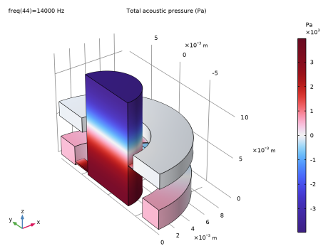
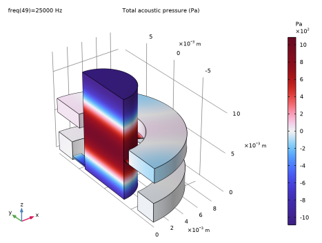
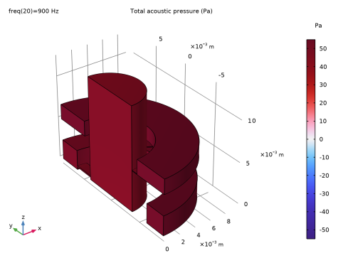
In the Settings window for Volume, click Replace Expression in the upper-right corner of the Expression section. From the menu, choose Component 1 (comp1) > Multiphysics > atb1.p_t - Total acoustic pressure - Pa.
|
|
3
|
|
4
|
|
1
|
|
2
|
|
3
|
|
4
|
|
5
|
|
6
|
|
7
|
|
8
|
|
1
|
|
2
|
|
3
|
|
4
|
|
5
|
|
7
|
|
8
|
Locate the Coloring and Style section. Find the Line style subsection. From the Type list, choose Tube.
|
|
1
|
|
2
|
|
3
|
|
4
|
|
5
|
|
6
|
|
7
|
|
8
|
|
9
|
|
1
|
|
2
|
|
3
|
|
4
|
Locate the Plot Settings section.
|
|
5
|
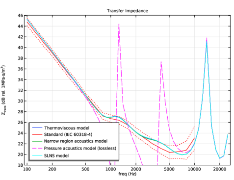
Select the y-axis label checkbox. In the associated text field, type Z<sub>trans</sub> (dB rel. 1MPa·s/m<sup>3</sup>).
|
|
6
|
|
1
|
|
2
|
|
1
|
|
2
|
|
4
|
|
5
|
Locate the Data section. From the Dataset list, choose Study 1 - Thermoviscous Model/Solution 1 (sol1).
|
|
6
|
|
7
|
In the Parameter values list, choose values from 100 to 10000.
|
|
8
|
|
9
|
|
1
|
|
2
|
|
4
|
Locate the Coloring and Style section. Find the Line style subsection. From the Line list, choose Dotted.
|
|
5
|
|
1
|
In the Model Builder window, under Results > Transfer Impedance right-click Global 1 and choose Duplicate.
|
|
2
|
|
3
|
|
4
|
Locate the y-Axis Data section. In the table, enter the following settings:
|
|
5
|
|
1
|
|
2
|
|
3
|
|
4
|
Locate the y-Axis Data section. In the table, enter the following settings:
|
|
5
|
|
6
|
|
1
|
|
2
|
|
3
|
|
4
|
Locate the y-Axis Data section. In the table, enter the following settings:
|
|
5
|
|
6
|
|
7
|
|
1
|
|
2
|
|
3
|
Select the Manual axis limits checkbox.
|
|
4
|
|
5
|
|
1
|
|
2
|
|
3
|
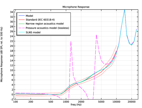
Locate the Plot Settings section. In the y-axis label text field, type Microphone Response (dB SPL rel. to 500 Hz).
|
|
4
|
|
1
|
|
2
|
|
1
|
|
2
|
|
1
|
|
2
|
|
1
|
|
2
|
|
1
|
|
2
|
|
1
|
|
2
|
|
1
|
|
2
|
|
3
|
|
4
|
|
5
|
|
1
|
|
2
|
|
3
|
|
4
|
Locate the Plot Settings section.
|
|
5
|
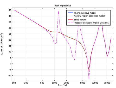
Select the y-axis label checkbox. In the associated text field, type Z<sub>in</sub> (dB rel. 1MPa·s/m<sup>3</sup>).
|
|
1
|
|
2
|
|
1
|
|
2
|
|
3
|
|
4
|
Locate the y-Axis Data section. In the table, enter the following settings:
|
|
1
|
|
2
|
|
3
|
|
4
|
Locate the y-Axis Data section. In the table, enter the following settings:
|
|
1
|
|
2
|
|
3
|
|
4
|
Locate the y-Axis Data section. In the table, enter the following settings:
|
|
5
|
|
6
|
|
7
|
|
8
|
|
1
|
|
2
|
|
3
|
|
4
|
|
1
|
|
2
|
|
4
|
|
5
|