|
|
|
|
108 N/m
|
||
|
•
|
|
•
|
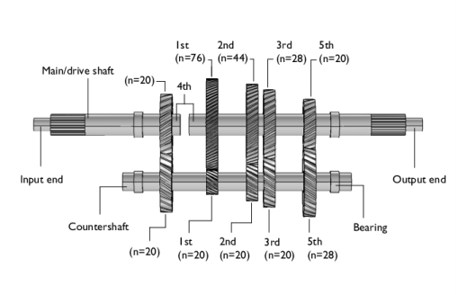
An external torque/load of 1000 Nm is applied at the output end of the drive shaft
|
|
•
|
|
•
|
|
•
|
|
•
|
|
1
|
|
2
|
|
3
|
Click Add.
|
|
4
|
Click
|
|
5
|
|
6
|
Click
|
|
1
|
|
2
|
|
3
|
Click
|
|
4
|
Browse to the model’s Application Libraries folder and double-click the file gearbox_vibration_noise.mphbin.
|
|
1
|
|
2
|
|
3
|
|
4
|
Clear the Create pairs checkbox.
|
|
5
|
|
6
|
|
7
|
|
8
|
On the object fin, select Domain 4 only.
|
|
9
|
|
10
|
|
11
|
|
12
|
Clear the Automatic detection of small details checkbox.
|
|
13
|
|
1
|
|
2
|
|
3
|
Click
|
|
4
|
Browse to the model’s Application Libraries folder and double-click the file gearbox_vibration_noise_parameters.txt.
|
|
1
|
|
2
|
|
3
|
|
1
|
|
2
|
|
3
|
|
4
|
|
1
|
|
2
|
|
3
|
|
4
|
Click
|
|
5
|
|
6
|
Click OK.
|
|
1
|
|
2
|
|
3
|
Click
|
|
4
|
Click
|
|
5
|
|
6
|
Click OK.
|
|
1
|
|
2
|
|
3
|
Click
|
|
4
|
Click
|
|
5
|
|
6
|
Click OK.
|
|
1
|
|
2
|
|
3
|
Click
|
|
4
|
Click
|
|
5
|
|
6
|
Click OK.
|
|
1
|
|
2
|
|
3
|
Click
|
|
4
|
Click
|
|
5
|
In the Paste Selection dialog, type 184-190, 193-209, 214-217, 226-240, 242-246, 533-540, 602-613, 677-680, 683-690 in the Selection text field.
|
|
6
|
Click OK.
|
|
1
|
|
2
|
|
3
|
|
4
|
Click
|
|
5
|
|
6
|
Click OK.
|
|
7
|
|
8
|
|
1
|
|
2
|
|
3
|
|
4
|
|
1
|
|
2
|
Go to the Add Material window.
|
|
3
|
|
4
|
Click the Add to Component button in the window toolbar.
|
|
5
|
|
1
|
|
3
|
In the Settings window for Helical Gear, type Helical Gear: Fourth (Counter Shaft) in the Label text field.
|
|
4
|
|
5
|
|
6
|
|
7
|
|
8
|
|
1
|
|
2
|
In the Settings window for Rigid Material, type Rigid Material: Counter Shaft in the Label text field.
|
|
1
|
|
2
|
|
3
|
|
4
|
|
1
|
|
2
|
In the Settings window for Helical Gear, type Helical Gear: Fourth (Main Shaft) in the Label text field.
|
|
3
|
|
5
|
|
6
|
|
7
|
|
1
|
|
2
|
In the Settings window for Rigid Material, type Rigid Material: Main Input Shaft in the Label text field.
|
|
1
|
|
2
|
In the Settings window for Rigid Material, type Rigid Material: Main Output Shaft in the Label text field.
|
|
3
|
|
1
|
In the Model Builder window, under Component 1 (comp1) > Multibody Dynamics (mbd) right-click Fixed Joint 5 and choose Duplicate.
|
|
2
|
|
3
|
|
4
|
|
1
|
|
2
|
|
3
|
|
4
|
|
1
|
|
2
|
|
3
|
|
4
|
|
1
|
In the Model Builder window, under Component 1 (comp1) > Multibody Dynamics (mbd) click Hinge Joint 5.
|
|
2
|
|
3
|
|
1
|
|
2
|
|
3
|
Click
|
|
4
|
|
5
|
Click OK.
|
|
1
|
|
2
|
|
3
|
|
4
|
|
5
|
|
1
|
|
2
|
|
3
|
|
4
|
|
5
|
|
6
|
|
1
|
|
2
|
In the Settings window for Attachment, type Attachment: Bearing 1 (Counter Shaft) in the Label text field.
|
|
3
|
|
1
|
|
2
|
|
3
|
|
4
|
|
1
|
|
2
|
|
3
|
|
4
|
|
1
|
|
2
|
|
3
|
From the list, choose Joint.
|
|
4
|
|
1
|
|
2
|
|
3
|
|
4
|
|
1
|
In the Model Builder window, under Component 1 (comp1) > Multibody Dynamics (mbd), Ctrl-click to select Helical Gear: Fourth (Counter Shaft), Helical Gear: First (Counter Shaft), Helical Gear: Second (Counter Shaft), Helical Gear: Third (Counter Shaft), Helical Gear: Fifth (Counter Shaft), Helical Gear: Fourth (Main Shaft), Helical Gear: First (Main Shaft), Helical Gear: Second (Main Shaft), Helical Gear: Third (Main Shaft), and Helical Gear: Fifth (Main Shaft).
|
|
2
|
Right-click and choose Group.
|
|
1
|
|
2
|
|
1
|
In the Model Builder window, under Component 1 (comp1) > Multibody Dynamics (mbd), Ctrl-click to select Gear Pair: Fourth, Gear Pair: First, Gear Pair: Second, Gear Pair: Third, and Gear Pair: Fifth.
|
|
2
|
Right-click and choose Group.
|
|
1
|
In the Model Builder window, collapse the Component 1 (comp1) > Multibody Dynamics (mbd) > Gear Pairs node.
|
|
2
|
|
3
|
Drag and drop below Helical Gears.
|
|
1
|
In the Model Builder window, under Component 1 (comp1) > Multibody Dynamics (mbd), Ctrl-click to select Rigid Material: Counter Shaft, Rigid Material: Main Input Shaft, and Rigid Material: Main Output Shaft.
|
|
2
|
Right-click and choose Group.
|
|
1
|
|
2
|
|
1
|
In the Model Builder window, under Component 1 (comp1) > Multibody Dynamics (mbd), Ctrl-click to select Attachment: Bearing 1 (Counter Shaft), Attachment: Bearing 1 (Main Shaft), Attachment: Bearing 2 (Counter Shaft), and Attachment: Bearing 2 (Main Shaft).
|
|
2
|
Right-click and choose Group.
|
|
1
|
|
2
|
|
1
|
In the Model Builder window, under Component 1 (comp1) > Multibody Dynamics (mbd), Ctrl-click to select Fixed Joint 1, Fixed Joint 2, Fixed Joint 3, Fixed Joint 4, Fixed Joint 5, and Fixed Joint 6.
|
|
2
|
Right-click and choose Group.
|
|
1
|
|
2
|
|
1
|
In the Model Builder window, under Component 1 (comp1) > Multibody Dynamics (mbd), Ctrl-click to select Hinge Joint 1, Hinge Joint 2, Hinge Joint 3, Hinge Joint 4, Hinge Joint 5, Hinge Joint 6, Hinge Joint 7, Hinge Joint 8, and Hinge Joint 9.
|
|
2
|
Right-click and choose Group.
|
|
1
|
|
2
|
|
1
|
|
2
|
|
1
|
|
2
|
|
3
|
|
4
|
Click
|
|
1
|
|
2
|
|
1
|
|
2
|
|
3
|
|
1
|
|
2
|
|
3
|
|
4
|
|
5
|
|
1
|
|
2
|
|
1
|
|
2
|
|
3
|
|
4
|
Click
|
|
5
|
|
6
|
Click OK.
|
|
1
|
In the Model Builder window, expand the Study: Multibody Analysis/Solution 1 (3) (sol1) node, then click Selection.
|
|
2
|
|
3
|
Click
|
|
4
|
Click
|
|
5
|
|
6
|
Click OK.
|
|
1
|
|
2
|
|
1
|
|
2
|
|
3
|
|
4
|
|
5
|
|
1
|
|
2
|
|
3
|
|
1
|
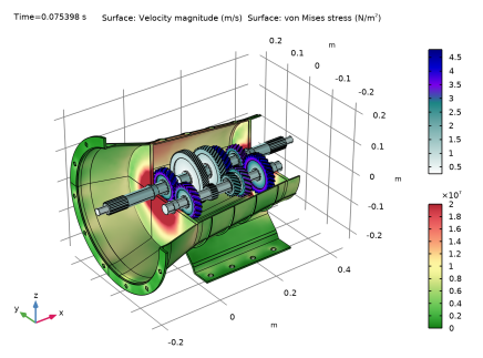
In the Model Builder window, under Results > Velocity - Stress right-click Surface 1 and choose Duplicate.
|
|
2
|
|
3
|
|
4
|
|
5
|
|
6
|
|
7
|
|
8
|
|
1
|
|
2
|
|
3
|
|
4
|
|
5
|
|
1
|
|
2
|
|
3
|
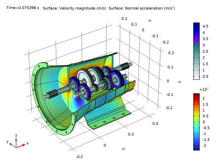
In the Settings window for 3D Plot Group, type Velocity - Normal Acceleration in the Label text field.
|
|
1
|
In the Model Builder window, expand the Results > Velocity - Normal Acceleration > Surface 2 node, then click Surface 2.
|
|
2
|
|
3
|
|
4
|
|
5
|
|
6
|
|
7
|
|
1
|
|
2
|
|
1
|
|
2
|
|
3
|
Click
|
|
4
|
|
5
|
Click OK.
|
|
6
|
|
7
|
|
8
|
|
9
|
|
10
|
|
11
|
|
12
|
|
13
|
|
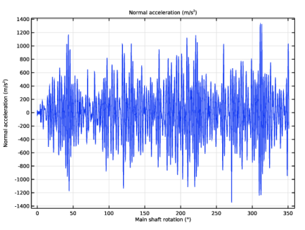
1
|
|
2
|
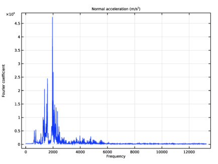
In the Settings window for 1D Plot Group, type Normal Acceleration: Frequency in the Label text field.
|
|
1
|
In the Model Builder window, expand the Normal Acceleration: Frequency node, then click Point Graph 1.
|
|
2
|
|
3
|
|
4
|
|
5
|
|
6
|
|
1
|
|
2
|
|
1
|
|
2
|
|
3
|
Click
|
|
4
|
Browse to the model’s Application Libraries folder and double-click the file gearbox_vibration_noise.mphbin.
|
|
1
|
|
2
|
Click in the Graphics window and then press Ctrl+A to select all objects.
|
|
1
|
|
2
|
|
3
|
|
1
|
|
2
|
Select the object sph1 only.
|
|
3
|
|
4
|
|
5
|
Select the object csol1 only.
|
|
1
|
|
2
|
|
3
|
|
4
|
|
5
|
|
6
|
On the object fin, select Boundary 2 only.
|
|
7
|
|
8
|
|
9
|
|
10
|
Clear the Automatic detection of small details checkbox.
|
|
1
|
|
2
|
|
3
|
|
4
|
|
5
|
Click
|
|
6
|
|
7
|
Click OK.
|
|
1
|
|
2
|
|
3
|
|
4
|
Click
|
|
5
|
In the Paste Selection dialog, type 12-20, 23-40, 43-47, 49, 53-73, 127, 132-134, 139, 144-193, 196-202, 205-207, 210-220, 223-229, 232-234, 237-244, 280-297, 299-318, 320-348, 351-356, 358-359, 361-681, 711-712, 715-720, 723-724, 727-734 in the Selection text field.
|
|
6
|
Click OK.
|
|
1
|
|
2
|
Go to the Add Material window.
|
|
3
|
|
4
|
Click the Add to Component button in the window toolbar.
|
|
5
|
|
1
|
|
2
|
Go to the Add Physics window.
|
|
3
|
|
4
|
Find the Physics interfaces in study subsection. In the table, clear the Solve checkbox for Study: Multibody Analysis.
|
|
5
|
Click the Add to Component 2 button in the window toolbar.
|
|
6
|
|
1
|
In the Settings window for Pressure Acoustics, Frequency Domain, click to expand the Discretization section.
|
|
2
|
|
1
|
|
2
|
|
3
|
|
1
|
|
2
|
|
3
|
|
4
|
|
5
|
In the Show More Options dialog, in the tree, select the checkbox for the node Physics > Advanced Physics Options.
|
|
6
|
Click OK.
|
|
7
|
In the Settings window for Exterior Field Calculation, click to expand the Advanced Settings section.
|
|
8
|
Clear the Use polynomial-preserving recovery for the normal gradient checkbox.
|
|
1
|
|
2
|
|
3
|
|
4
|
|
5
|
|
1
|
|
2
|
|
3
|
Click the Custom button.
|
|
4
|
Locate the Element Size Parameters section. In the Maximum element size text field, type 343/3000/4.
|
|
1
|
|
2
|
In the Settings window for Boundary Layer Properties, locate the Geometric Entity Selection section.
|
|
3
|
|
4
|
|
5
|
|
1
|
|
2
|
Go to the Add Study window.
|
|
3
|
|
4
|
Click the Add Study button in the window toolbar.
|
|
5
|
|
1
|
|
2
|
Clear the Generate default plots checkbox.
|
|
3
|
|
1
|
|
2
|
|
3
|
|
4
|
|
5
|
|
6
|
Locate the Physics and Variables Selection section. In the Solve for column of the table, under Component 2 (comp2), clear the checkbox for Pressure Acoustics, Frequency Domain (acpr).
|
|
1
|
|
2
|
|
3
|
|
4
|
Locate the Physics and Variables Selection section. In the Solve for column of the table, under Component 1 (comp1), clear the checkbox for Multibody Dynamics (mbd).
|
|
5
|
Click to expand the Values of Dependent Variables section. Find the Values of variables not solved for subsection. From the Settings list, choose User controlled.
|
|
6
|
|
7
|
|
8
|
|
1
|
|
2
|
|
3
|
In the Model Builder window, expand the Study: Acoustics (Frequency Domain) > Solver Configurations > Solution 2 (sol2) > Dependent Variables 2 node, then click Acoustic Pressure (comp2.p).
|
|
4
|
|
5
|
|
6
|
|
7
|
In the Model Builder window, under Study: Acoustics (Frequency Domain) > Solver Configurations > Solution 2 (sol2) click Stationary Solver 1.
|
|
8
|
|
9
|
|
10
|
|
1
|
|
2
|
|
3
|
|
4
|
|
1
|
|
2
|
|
3
|
|
4
|
|
5
|
|
1
|
|
2
|
|
3
|
|
4
|
|
5
|
|
6
|
|
1
|
|
2
|
|
3
|
|
4
|
|
5
|
|
6
|
|
1
|
|
2
|
|
3
|
|
4
|
|
5
|
|
6
|
|
1
|
|
2
|
|
3
|
|
4
|
|
5
|
|
1
|
|
2
|
|
3
|
|
4
|
|
5
|
|
6
|
|
7
|
|
1
|
|
2
|
|
3
|
Locate the Data section. From the Dataset list, choose Study: Acoustics (Frequency Domain)/Solution 2 (5) (sol2).
|
|
4
|
|
5
|
|
6
|
|
7
|
|
1
|
|
2
|
|
3
|
|
4
|
|
5
|
|
6
|
|
1
|
|
2
|
|
3
|
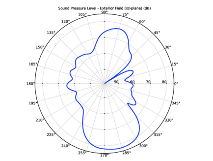
Locate the Title section. In the Title text area, type Sound Pressure Level - Exterior Field (xz-plane) (dB).
|
|
1
|
|
2
|
|
3
|
|
4
|
|
5
|
|
6
|
|
1
|
|
2
|
|
3
|
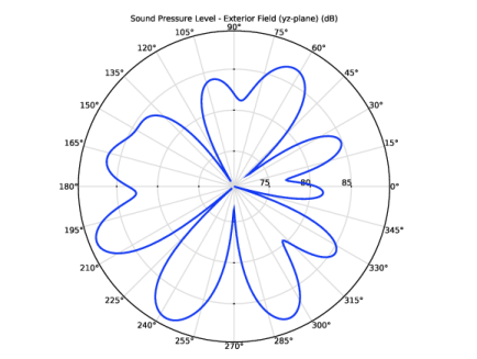
Locate the Title section. In the Title text area, type Sound Pressure Level - Exterior Field (yz-plane) (dB).
|
|
1
|
|
2
|
|
3
|
|
4
|
|
5
|
|
6
|
|
1
|
|
2
|
|
3
|
Click
|
|
4
|
Browse to the model’s Application Libraries folder and double-click the file gearbox_vibration_noise_results_parameters.txt.
|
|
1
|
|
2
|
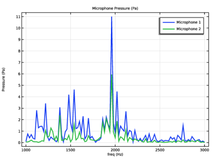
In the Settings window for Global Evaluation, type Global Evaluation: Microphone 1 in the Label text field.
|
|
3
|
Locate the Data section. From the Dataset list, choose Study: Acoustics (Frequency Domain)/Solution 2 (5) (sol2).
|
|
4
|
Locate the Expressions section. In the table, enter the following settings:
|
|
5
|
Click
|
|
1
|
|
2
|
In the Settings window for Global Evaluation, type Global Evaluation: Microphone 2 in the Label text field.
|
|
3
|
Locate the Expressions section. In the table, enter the following settings:
|
|
4
|
|
1
|
|
2
|
|
3
|
Locate the Data section. From the Dataset list, choose Study: Acoustics (Frequency Domain)/Solution 2 (5) (sol2).
|
|
4
|
|
5
|
|
6
|
Locate the Plot Settings section.
|
|
7
|
|
1
|
|
2
|
|
4
|
|
5
|
|
6
|
|
1
|
|
2
|
Go to the Add Study window.
|
|
3
|
|
4
|
Click the Add Study button in the window toolbar.
|
|
5
|
|
1
|
|
2
|
|
1
|
|
2
|
|
3
|
|
4
|
|
5
|
Locate the Physics and Variables Selection section. In the Solve for column of the table, under Component 1 (comp1), clear the checkbox for Multibody Dynamics (mbd).
|
|
6
|
|
1
|
|
2
|
|
3
|
Locate the Data section. From the Dataset list, choose Study: Acoustics (Time Domain)/Solution 3 (8) (sol3).
|
|
1
|
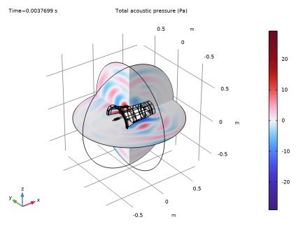
In the Model Builder window, expand the Results > Pressure Near Field: Time node, then click Slice 1.
|
|
2
|
|
3
|
|
4
|
|
1
|
|
2
|
|
3
|
|
4
|
|
5
|
|
6
|
|
1
|
|
2
|
|
3
|
|
4
|
|
1
|
|
2
|
|
3
|
|
1
|
|
2
|
|
3
|
|
4
|
|
5
|
|
1
|
|
2
|
|
3
|
|
1
|
|
2
|
|
3
|
|
1
|
|
2
|
|
3
|
|
1
|
|
2
|
|
3
|
Click OK.
|
|
1
|
In the Application Builder window, under Methods right-click Microphone1 and choose Indent and Format.
|
|
2
|
Copy the following code into the Microphone1 window:
|
|
1
|
|
2
|
|
3
|
Click OK.
|
|
1
|
In the Application Builder window, under Methods right-click Microphone2 and choose Indent and Format.
|
|
2
|
Copy the following code into the Microphone2 window:
|
|
1
|
|
2
|
|
3
|
|
1
|
|
2
|
|
1
|
|
2
|
|
3
|
|
1
|
|
2
|
|
3
|
|
4
|
|
5
|
|
6
|
|
1
|
|
2
|
|
3
|
|
4
|