|
|
|
|
•
|
|
•
|
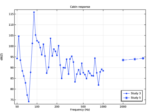
In the low-frequency range (below 1000 Hz) the model is solved using the default direct solver. The Block low rank factorization option is turned on as it improves the solver performance in this case.
|
|
1
|
|
2
|
In the Select Physics tree, select Acoustics > Pressure Acoustics > Pressure Acoustics, Frequency Domain (acpr).
|
|
3
|
Click Add.
|
|
4
|
|
5
|
Click Add.
|
|
6
|
Click Add.
|
|
7
|
Click
|
|
8
|
|
9
|
Click
|
|
1
|
|
2
|
|
3
|
|
4
|
|
1
|
|
2
|
|
3
|
Click
|
|
4
|
Browse to the model’s Application Libraries folder and double-click the file car_cabin_acoustics_geometry.mphbin.
|
|
1
|
|
2
|
|
3
|
On the object imp1, select Edges 53, 54, 56, 57, 389, 390, 392, and 393 only.
|
|
1
|
|
2
|
|
3
|
|
4
|
|
5
|
|
1
|
|
2
|
Select the object pt1 only.
|
|
3
|
|
4
|
|
5
|
|
6
|
|
7
|
|
8
|
Locate the Selections of Resulting Entities section. Select the Resulting objects selection checkbox.
|
|
9
|
|
10
|
|
11
|
Click OK.
|
|
1
|
In the Model Builder window, expand the Component 1 (comp1) > Geometry 1 > Cumulative Selections node, then click Microphone Array (Domain).
|
|
2
|
|
3
|
Clear the Show in physics checkbox.
|
|
1
|
|
2
|
|
3
|
Clear the Show in physics checkbox.
|
|
1
|
|
2
|
|
3
|
Clear the Show in physics checkbox.
|
|
1
|
|
2
|
|
3
|
|
4
|
On the object ige1, select Boundaries 3, 4, 62, 63, 507, 515, 807, 814, 838, 841, 844, and 845 only.
|
|
1
|
|
2
|
|
3
|
|
4
|
|
5
|
In the Paste Selection dialog, type ige1: 1, 2, 5-9, 11-30, 42-44, 47-52, 54-57, 64-71, 85-92, 95-97, 99-109, 115-119, 121-127, 130-145, 147-150, 152, 153, 162-166, 328-330, 335-339, 341, 792, 839 in the Selection text field.
|
|
6
|
Click OK.
|
|
1
|
|
2
|
|
3
|
|
4
|
On the object ige1, select Boundary 10 only.
|
|
1
|
|
2
|
|
3
|
|
4
|
|
5
|
In the Paste Selection dialog, type ige1: 155, 157-161, 167, 168, 175, 176, 181-203, 212-215, 218-236, 259, 261-267, 273, 281, 282, 284, 285, 296-310, 314, 322-327, 367-370, 373-386, 389-400, 413, 414, 435, 436, 445, 446, 458, 509, 519-587, 593, 594, 607-620, 639-644, 647-661, 663-672, 680-691, 695, 697-706 in the Selection text field.
|
|
6
|
Click OK.
|
|
1
|
|
2
|
|
3
|
|
4
|
|
5
|
In the Paste Selection dialog, type ige1: 204, 205, 208, 209, 216, 217, 237, 238, 240-242, 245, 246, 249, 250, 253-256, 282, 288-295, 310, 311, 314-317, 343-352, 357-366, 371, 372, 387, 388, 395, 401-412, 417-434, 437-444, 447-453, 467-473, 483-494, 588, 589, 591, 592, 595-606, 621, 622, 628-638, 673-679, 686, 695, 696, 707, 708, 723, 734-747, 752-774, 783-790, 793-802, 816-835 in the Selection text field.
|
|
6
|
Click OK.
|
|
1
|
|
2
|
|
3
|
|
4
|
|
5
|
|
6
|
Click OK.
|
|
1
|
|
2
|
|
3
|
|
4
|
On the object ige1, select Boundaries 33, 36, 171, and 174 only.
|
|
1
|
|
2
|
|
3
|
|
4
|
On the object ige1, select Boundaries 169, 170, 177, and 178 only.
|
|
1
|
|
2
|
|
3
|
|
4
|
On the object ige1, select Boundaries 172, 173, 179, and 180 only.
|
|
1
|
|
2
|
|
3
|
|
4
|
On the object ige1, select Boundaries 39 and 40 only.
|
|
1
|
|
2
|
|
3
|
|
4
|
On the object ige1, select Boundaries 37 and 38 only.
|
|
1
|
|
2
|
|
3
|
|
4
|
|
5
|
Click OK.
|
|
6
|
|
1
|
|
2
|
|
3
|
Select the Ambient occlusion checkbox.
|
|
1
|
|
2
|
|
3
|
|
4
|
Browse to the model’s Application Libraries folder and double-click the file car_cabin_acoustics_parameters_model.txt.
|
|
1
|
|
2
|
|
3
|
|
4
|
Browse to the model’s Application Libraries folder and double-click the file car_cabin_acoustics_parameters_boundaries.txt.
|
|
1
|
|
2
|
|
3
|
|
4
|
Browse to the model’s Application Libraries folder and double-click the file car_cabin_acoustics_parameters_midwoofer.txt.
|
|
1
|
|
2
|
|
3
|
|
4
|
Browse to the model’s Application Libraries folder and double-click the file car_cabin_acoustics_parameters_tweeter.txt.
|
|
1
|
|
2
|
In the Settings window for Interpolation, type Interpolation 1 - Leather Seats in the Label text field.
|
|
3
|
|
4
|
Click
|
|
5
|
Browse to the model’s Application Libraries folder and double-click the file car_cabin_acoustics_impedance_seats.txt.
|
|
6
|
Locate the Data Column Settings section. In the table, click to select the cell at row number 1 and column number 1.
|
|
7
|
|
10
|
|
11
|
|
13
|
|
14
|
|
15
|
Locate the Interpolation and Extrapolation section. From the Interpolation list, choose Piecewise cubic.
|
|
16
|
|
1
|
|
2
|
In the Settings window for Analytic, type Analytic 1 - Struve Function (Order One) in the Label text field.
|
|
3
|
|
4
|
Locate the Definition section. In the Expression text field, type 2/pi-besselj(0,x)+(16/pi-5)*sin(x)/x+(12-36/pi)*(1-cos(x))/x^2.
|
|
5
|
|
7
|
Click to expand the Advanced section. Select the May produce complex output for real arguments checkbox.
|
|
8
|
Locate the Plot Parameters section. In the table, enter the following settings:
|
|
1
|
|
2
|
|
3
|
|
4
|
Locate the Definition section. In the Expression text field, type rho0*c0*(1-besselj(1,2*x)/x+i*h1(2*x)/x).
|
|
5
|
|
7
|
|
8
|
Locate the Plot Parameters section. In the table, enter the following settings:
|
|
1
|
|
2
|
Go to the Add Material window.
|
|
3
|
|
4
|
Click the Add to Component button in the window toolbar.
|
|
5
|
|
1
|
In the Model Builder window, under Component 1 (comp1) right-click Definitions and choose Variables.
|
|
2
|
|
3
|
|
4
|
Browse to the model’s Application Libraries folder and double-click the file car_cabin_acoustics_variables_acoustics.txt.
|
|
1
|
|
2
|
In the Settings window for Variables, type Variables 2 - Electrical Circuits in the Label text field.
|
|
3
|
|
4
|
Browse to the model’s Application Libraries folder and double-click the file car_cabin_acoustics_variables_electrical_circuits.txt.
|
|
1
|
|
2
|
|
3
|
|
4
|
Select the All boundaries checkbox.
|
|
1
|
|
2
|
|
3
|
|
4
|
|
5
|
|
6
|
Click OK.
|
|
7
|
|
8
|
|
9
|
In the Add dialog, in the Selections to subtract list, choose Windows, Dashboard, Carpet floor, Doors, Leather seats, Roof trim, Speaker Covers, Midwoofer L, Midwoofer R, Tweeter R, and Tweeter L.
|
|
10
|
Click OK.
|
|
1
|
|
2
|
|
3
|
|
4
|
|
5
|
In the Add dialog, in the Selections to add list, choose Midwoofer L, Midwoofer R, Tweeter R, and Tweeter L.
|
|
6
|
Click OK.
|
|
1
|
In the Model Builder window, under Component 1 (comp1) > Pressure Acoustics, Frequency Domain (acpr) click Pressure Acoustics 1.
|
|
2
|
|
3
|
|
4
|
|
1
|
|
2
|
|
3
|
|
4
|
|
5
|
|
1
|
|
2
|
|
3
|
|
4
|
|
5
|
|
1
|
|
2
|
|
3
|
|
4
|
|
5
|
|
6
|
|
7
|
|
8
|
Locate the Porous Matrix Properties section. From the Porous elastic material list, choose Air (mat1).
|
|
9
|
|
10
|
|
1
|
|
2
|
|
3
|
|
4
|
|
5
|
|
1
|
|
2
|
|
3
|
|
4
|
|
1
|
|
2
|
|
3
|
|
4
|
|
5
|
|
6
|
|
7
|
|
8
|
Locate the Porous Matrix Properties section. From the Porous elastic material list, choose Air (mat1).
|
|
9
|
|
10
|
|
1
|
|
2
|
|
3
|
|
4
|
|
5
|
|
1
|
|
2
|
In the Settings window for Lumped Speaker Boundary, type Lumped Speaker Boundary 1 - Midwoofer L in the Label text field.
|
|
3
|
|
4
|
|
1
|
|
2
|
In the Settings window for Lumped Speaker Boundary, type Lumped Speaker Boundary 2 - Tweeter R in the Label text field.
|
|
3
|
|
4
|
|
1
|
|
2
|
In the Settings window for Electrical Circuit, type Electrical Circuit - Midwoofer in the Label text field.
|
|
1
|
|
2
|
|
4
|
|
1
|
|
2
|
|
4
|
|
1
|
|
2
|
|
4
|
|
1
|
|
2
|
|
4
|
Locate the Current Measurement section. From the Measure current for device list, choose Inductor 2 (L2).
|
|
5
|
|
1
|
|
2
|
|
4
|
Locate the Current Measurement section. From the Measure current for device list, choose Resistor 1 (R1).
|
|
5
|
|
1
|
|
2
|
|
4
|
|
1
|
|
2
|
|
4
|
|
1
|
|
2
|
|
4
|
|
1
|
|
2
|
|
3
|
|
4
|
Locate the Node Connections section. In the table, enter the following settings:
|
|
1
|
|
2
|
|
4
|
Locate the Voltage Measurement section. In the table, enter the following settings:
|
|
5
|
|
1
|
|
2
|
|
4
|
Locate the Current Measurement section. From the Measure current for device list, choose Voltage-Controlled Voltage Source 1 (E1).
|
|
5
|
|
1
|
In the Model Builder window, under Component 1 (comp1) > Electrical Circuit - Midwoofer (cir) click Resistor 3 (R3).
|
|
2
|
In the Settings window for Resistor, type Resistor 3 - Lumped Radiation Impedance in the Label text field.
|
|
3
|
Locate the Node Connections section. In the table, enter the following settings:
|
|
4
|
|
5
|
Locate the Node Connections section. In the table, enter the following settings:
|
|
1
|
In the Model Builder window, under Component 1 (comp1) > Electrical Circuit - Midwoofer (cir) click Resistor 4 (R4).
|
|
2
|
In the Settings window for Resistor, type Resistor 4 - Lumped Back Volume Compliance in the Label text field.
|
|
3
|
Locate the Node Connections section. In the table, enter the following settings:
|
|
4
|
|
1
|
|
2
|
In the Settings window for Electrical Circuit, type Electrical Circuit 2 - Tweeter in the Label text field.
|
|
1
|
In the Model Builder window, under Component 1 (comp1) > Electrical Circuit - Midwoofer (cir), Ctrl-click to select Voltage Source 1 (V1), Resistor 1 (R1), Inductor 1 (L1), Current-Controlled Voltage Source 1 (H1), Current-Controlled Voltage Source 2 (H2), Inductor 2 (L2), Resistor 2 (R2), Capacitor 1 (C1), External I vs. U 1 (IvsU1), Voltage-Controlled Voltage Source 1 (E1), Current-Controlled Current Source 1 (F1), Resistor 3 - Lumped Radiation Impedance (R3), and Resistor 4 - Lumped Back Volume Compliance (R4).
|
|
2
|
Right-click and choose Copy.
|
|
1
|
|
1
|
|
2
|
|
4
|
|
1
|
|
2
|
|
4
|
|
1
|
|
2
|
|
4
|
Locate the Current Measurement section. From the Measure current for device list, choose Inductor 2 (L2).
|
|
5
|
|
1
|
|
2
|
|
4
|
|
1
|
|
2
|
|
4
|
|
1
|
|
2
|
|
4
|
|
1
|
|
2
|
|
4
|
|
1
|
|
2
|
|
3
|
|
4
|
Locate the Node Connections section. In the table, enter the following settings:
|
|
1
|
|
2
|
|
4
|
Locate the Voltage Measurement section. In the table, enter the following settings:
|
|
5
|
|
1
|
|
2
|
|
4
|
|
1
|
|
2
|
|
4
|
|
1
|
|
2
|
|
4
|
|
1
|
|
2
|
|
3
|
Locate the Physics-Controlled Mesh section. In the table, clear the Use checkboxes for Geometric Analysis, Detail Size and Pressure Acoustics, Frequency Domain (acpr).
|
|
4
|
Click
|
|
1
|
|
2
|
|
1
|
|
2
|
|
3
|
Click
|
|
4
|
|
5
|
|
6
|
|
7
|
|
8
|
Click Replace.
|
|
9
|
|
10
|
Select the Modify model configuration for study step checkbox.
|
|
11
|
|
12
|
Click
|
|
13
|
In the tree, select Component 1 (comp1) > Electrical Circuit - Midwoofer (cir) > External I vs. U 1 (IvsU1).
|
|
14
|
Click
|
|
15
|
In the tree, select Component 1 (comp1) > Electrical Circuit 2 - Tweeter (cir2) > External I vs. U 1 (IvsU1).
|
|
16
|
Click
|
|
17
|
|
1
|
|
2
|
|
3
|
Select the Only plot when requested checkbox.
|
|
1
|
|
2
|
|
3
|
|
4
|
|
1
|
|
2
|
|
3
|
|
4
|
Locate the y-Axis Data section. In the Expression text field, type acpr.iomega*rho0*cir.R3.i*exp(-i*k0*1[m])/(2*pi*1[m]).
|
|
5
|
|
6
|
|
7
|
|
1
|
|
2
|
|
3
|
|
4
|
Locate the Legends section. In the table, enter the following settings:
|
|
5
|
|
1
|
|
2
|
Go to the Add Study window.
|
|
3
|
|
4
|
Click the Add Study button in the window toolbar.
|
|
5
|
|
6
|
Click the Add Study button in the window toolbar three times.
|
|
7
|
|
1
|
|
2
|
|
3
|
|
4
|
|
5
|
Locate the Pressure Acoustics, Frequency Domain (acpr) section. From the Maximum mesh element size control parameter list, choose Frequency.
|
|
6
|
|
1
|
In the Model Builder window, under Component 1 (comp1) > Meshes > Mesh 2 - Fixed Mesh for Frequency Sweeps click Size.
|
|
2
|
|
3
|
|
4
|
|
1
|
In the Settings window for Free Tetrahedral, click to expand the Element Quality Optimization section.
|
|
2
|
Select the Avoid elements that are too small checkbox.
|
|
3
|
|
4
|
In the Model Builder window, right-click Mesh 2 - Fixed Mesh for Frequency Sweeps and choose Duplicate.
|
|
1
|
In the Settings window for Mesh, type Mesh 3 - Adaptive Mesh for High Frequencies in the Label text field.
|
|
1
|
In the Model Builder window, expand the Mesh 3 - Adaptive Mesh for High Frequencies node, then click Size.
|
|
2
|
|
3
|
|
1
|
|
2
|
|
1
|
|
2
|
|
3
|
|
4
|
Locate the Physics and Variables Selection section. In the Solve for column of the table, under Component 1 (comp1), clear the checkboxes for Electrical Circuit - Midwoofer (cir) and Electrical Circuit 2 - Tweeter (cir2).
|
|
5
|
Click to expand the Mesh Selection section. In the table, enter the following settings:
|
|
6
|
|
1
|
|
2
|
|
3
|
|
4
|
|
5
|
|
6
|
|
7
|
|
8
|
|
1
|
|
2
|
|
3
|
|
4
|
|
5
|
|
6
|
|
7
|
|
8
|
|
9
|
|
1
|
|
2
|
In the Settings window for Study, type Study 3 - Frequency Sweep up to fmax in the Label text field.
|
|
3
|
|
1
|
In the Model Builder window, under Study 3 - Frequency Sweep up to fmax click Step 1: Frequency Domain.
|
|
2
|
|
3
|
Click
|
|
4
|
|
5
|
|
6
|
|
7
|
|
8
|
Click Replace.
|
|
9
|
|
10
|
Select the Modify model configuration for study step checkbox.
|
|
11
|
In the tree, select Component 1 (comp1) > Electrical Circuit - Midwoofer (cir) > Voltage-Controlled Voltage Source 1 (E1), Component 1 (comp1) > Electrical Circuit - Midwoofer (cir) > Current-Controlled Current Source 1 (F1), Component 1 (comp1) > Electrical Circuit - Midwoofer (cir) > Resistor 3 - Lumped Radiation Impedance (R3), and Component 1 (comp1) > Electrical Circuit - Midwoofer (cir) > Resistor 4 - Lumped Back Volume Compliance (R4).
|
|
12
|
Click
|
|
13
|
In the tree, select Component 1 (comp1) > Electrical Circuit 2 - Tweeter (cir2) > Voltage-Controlled Voltage Source 1 (E1), Component 1 (comp1) > Electrical Circuit 2 - Tweeter (cir2) > Current-Controlled Current Source 1 (F1), Component 1 (comp1) > Electrical Circuit 2 - Tweeter (cir2) > Resistor 3 - Lumped Radiation Impedance (R3), and Component 1 (comp1) > Electrical Circuit 2 - Tweeter (cir2) > Resistor 4 - Lumped Back Volume Compliance (R4).
|
|
14
|
Click
|
|
15
|
Click to expand the Store in Output section. In the table, enter the following settings:
|
|
16
|
|
17
|
|
18
|
Click OK.
|
|
19
|
|
1
|
|
2
|
|
3
|
In the Model Builder window, expand the Study 3 - Frequency Sweep up to fmax > Solver Configurations > Solution 3 (sol3) > Stationary Solver 1 node, then click Suggested Direct Solver (cir2_acpr_...).
|
|
4
|
|
5
|
Select the Block low rank factorization checkbox.
|
|
1
|
|
2
|
In the Settings window for Study, type Study 4 - Frequency Sweep up to fmax (Midwoofer Only) in the Label text field.
|
|
3
|
|
1
|
In the Model Builder window, under Study 4 - Frequency Sweep up to fmax (Midwoofer Only) click Step 1: Frequency Domain.
|
|
2
|
|
3
|
Click
|
|
4
|
|
5
|
|
6
|
|
7
|
|
8
|
Click Replace.
|
|
9
|
|
10
|
Select the Modify model configuration for study step checkbox.
|
|
11
|
In the tree, select Component 1 (comp1) > Pressure Acoustics, Frequency Domain (acpr) > Lumped Speaker Boundary 2 - Tweeter R.
|
|
12
|
Click
|
|
13
|
In the tree, select Component 1 (comp1) > Electrical Circuit - Midwoofer (cir) > Voltage-Controlled Voltage Source 1 (E1), Component 1 (comp1) > Electrical Circuit - Midwoofer (cir) > Current-Controlled Current Source 1 (F1), Component 1 (comp1) > Electrical Circuit - Midwoofer (cir) > Resistor 3 - Lumped Radiation Impedance (R3), and Component 1 (comp1) > Electrical Circuit - Midwoofer (cir) > Resistor 4 - Lumped Back Volume Compliance (R4).
|
|
14
|
Click
|
|
15
|
|
16
|
Click
|
|
17
|
Locate the Store in Output section. In the table, enter the following settings:
|
|
18
|
|
19
|
|
20
|
Click OK.
|
|
21
|
|
1
|
|
2
|
|
3
|
In the Model Builder window, expand the Study 4 - Frequency Sweep up to fmax (Midwoofer Only) > Solver Configurations > Solution 4 (sol4) > Stationary Solver 1 node, then click Suggested Direct Solver (acpr_cir).
|
|
4
|
|
5
|
Select the Block low rank factorization checkbox.
|
|
1
|
|
2
|
In the Settings window for Study, type Study 5 - Single Frequencies Above fmax in the Label text field.
|
|
3
|
|
1
|
|
2
|
|
3
|
Click
|
|
1
|
|
2
|
|
3
|
|
4
|
Locate the Physics and Variables Selection section. Select the Modify model configuration for study step checkbox.
|
|
5
|
In the tree, select Component 1 (comp1) > Electrical Circuit - Midwoofer (cir) > Voltage-Controlled Voltage Source 1 (E1), Component 1 (comp1) > Electrical Circuit - Midwoofer (cir) > Current-Controlled Current Source 1 (F1), Component 1 (comp1) > Electrical Circuit - Midwoofer (cir) > Resistor 3 - Lumped Radiation Impedance (R3), and Component 1 (comp1) > Electrical Circuit - Midwoofer (cir) > Resistor 4 - Lumped Back Volume Compliance (R4).
|
|
6
|
Click
|
|
7
|
In the tree, select Component 1 (comp1) > Electrical Circuit 2 - Tweeter (cir2) > Voltage-Controlled Voltage Source 1 (E1), Component 1 (comp1) > Electrical Circuit 2 - Tweeter (cir2) > Current-Controlled Current Source 1 (F1), Component 1 (comp1) > Electrical Circuit 2 - Tweeter (cir2) > Resistor 3 - Lumped Radiation Impedance (R3), and Component 1 (comp1) > Electrical Circuit 2 - Tweeter (cir2) > Resistor 4 - Lumped Back Volume Compliance (R4).
|
|
8
|
Click
|
|
9
|
Locate the Store in Output section. In the table, enter the following settings:
|
|
10
|
|
11
|
|
12
|
Click OK.
|
|
13
|
|
1
|
|
2
|
|
3
|
In the Model Builder window, expand the Study 5 - Single Frequencies Above fmax > Solver Configurations > Solution 5 (sol5) > Stationary Solver 1 node.
|
|
4
|
Right-click Study 5 - Single Frequencies Above fmax > Solver Configurations > Solution 5 (sol5) > Stationary Solver 1 > Suggested Iterative Solver (Shifted Laplace) (cir2_acpr_...) and choose Enable.
|
|
5
|
In the Model Builder window, expand the Study 5 - Single Frequencies Above fmax > Solver Configurations > Solution 5 (sol5) > Stationary Solver 1 > Suggested Iterative Solver (Shifted Laplace) (cir2_acpr_...) > Multigrid 1 > Coarse Solver node, then click Direct.
|
|
6
|
|
7
|
Select the Block low rank factorization checkbox.
|
|
1
|
|
2
|
Go to the Add Study window.
|
|
3
|
|
4
|
Click the Add Study button in the window toolbar.
|
|
5
|
|
1
|
|
2
|
|
1
|
|
2
|
|
3
|
Locate the Study Reference section. From the Study reference list, choose Study 3 - Frequency Sweep up to fmax.
|
|
1
|
|
2
|
|
3
|
Locate the Study Reference section. From the Study reference list, choose Study 4 - Frequency Sweep up to fmax (Midwoofer Only).
|
|
1
|
|
2
|
|
3
|
Locate the Study Reference section. From the Study reference list, choose Study 5 - Single Frequencies Above fmax.
|
|
4
|
|
1
|
|
2
|
|
3
|
|
4
|
|
5
|
|
1
|
|
2
|
|
3
|
|
4
|
|
6
|
|
7
|
Click to expand the Coloring and Style section. Find the Line markers subsection. From the Marker list, choose Point.
|
|
8
|
|
9
|
|
1
|
|
2
|
|
3
|
From the Dataset list, choose Study 5 - Single Frequencies Above fmax/Parametric Solutions 1 (sol7).
|
|
4
|
Locate the Coloring and Style section. Find the Line style subsection. From the Line list, choose Dashed.
|
|
5
|
|
6
|
|
7
|
Locate the Legends section. In the table, enter the following settings:
|
|
8
|
|
1
|
|
2
|
|
3
|
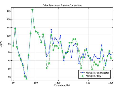
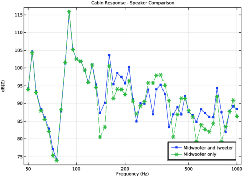
In the Settings window for 1D Plot Group, type Cabin Response - Speaker Comparison in the Label text field.
|
|
1
|
|
2
|
|
1
|
|
2
|
|
3
|
From the Dataset list, choose Study 4 - Frequency Sweep up to fmax (Midwoofer Only)/Solution 4 (sol4).
|
|
4
|
|
5
|
Locate the Legends section. In the table, enter the following settings:
|
|
6
|
|
1
|
|
2
|
Go to the Result Templates window.
|
|
3
|
In the tree, select Study 5 - Single Frequencies Above fmax/Parametric Solutions 1 (sol7) > Pressure Acoustics, Frequency Domain > Sound Pressure Level (acpr).
|
|
4
|
Click the Add Result Template button in the window toolbar.
|
|
5
|
|
1
|
|
2
|
|
3
|
Click
|
|
4
|
In the Paste Selection dialog, type 1, 2, 4-61, 63-256, 258-476, 478-488, 490-711, 713-808 in the Selection text field.
|
|
5
|
Click OK.
|
|
6
|
|
7
|
|
8
|
|
1
|
|
2
|
|
3
|
|
4
|
|
5
|
Click
|
|
6
|
Click
|
|
7
|
In the Paste Selection dialog, type 4, 7, 10, 64, 198, 199, 202, 203, 210, 211, 228, 229, 231-233, 236, 237, 240, 241, 244-247, 258, 269, 275-278, 293, 294, 297-300, 326-335, 340-349, 354, 355, 367, 368, 375, 381-392, 397-414, 417-424, 427-433, 449-455, 465-476, 478, 561, 562, 564, 565, 568-579, 594, 595, 601-607, 641-647, 654, 663, 664, 671, 672, 687, 698-711, 713, 716-738, 747-754, 756-766, 771, 777-796, 798, 799, 804, 805 in the Selection text field.
|
|
8
|
Click OK.
|
|
1
|
|
2
|
|
3
|
|
4
|
|
5
|
|
6
|
|
7
|
|
8
|