|
|
|

|
1
|
|
2
|
In the Select Physics tree, select Acoustics > Pressure Acoustics > Pressure Acoustics, Frequency Domain (acpr).
|
|
3
|
Click Add.
|
|
4
|
Click
|
|
5
|
|
6
|
Click
|
|
1
|
|
2
|
|
3
|
Click
|
|
4
|
Browse to the model’s Application Libraries folder and double-click the file acoustic_scattering_parameters.txt.
|
|
1
|
|
2
|
|
3
|
|
4
|
|
5
|
|
1
|
|
2
|
|
3
|
|
4
|
Click
|
|
5
|
Click the
|
|
6
|
|
1
|
|
2
|
Select the object sph1 only.
|
|
3
|
|
4
|
|
5
|
Select the object elp1 only.
|
|
6
|
Click
|
|
1
|
|
2
|
|
3
|
|
5
|
|
1
|
|
2
|
Go to the Add Material window.
|
|
3
|
|
4
|
Click the Add to Component button in the window toolbar.
|
|
5
|
|
1
|
In the Settings window for Pressure Acoustics, Frequency Domain, locate the Sound Pressure Level Settings section.
|
|
2
|
From the Reference pressure for the sound pressure level list, choose Use reference pressure for water.
|
|
1
|
|
3
|
|
4
|
|
5
|
|
6
|
|
7
|
|
1
|
|
2
|
|
3
|
|
1
|
|
2
|
|
3
|
|
1
|
|
2
|
|
3
|
|
1
|
|
2
|
|
3
|
|
4
|
Locate the Pressure Acoustics, Frequency Domain (acpr) section. From the Number of mesh elements per wavelength list, choose User defined.
|
|
6
|
Click
|
|
7
|
|
8
|
|
9
|
Click the
|
|
11
|
|
12
|
|
1
|
|
2
|
|
3
|
Clear the Generate default plots checkbox.
|
|
4
|
|
1
|
|
2
|
|
3
|
|
4
|
|
1
|
|
2
|
|
3
|
|
4
|
|
5
|
|
1
|
|
2
|
|
1
|
|
2
|
|
3
|
|
4
|
|
5
|
|
6
|
|
1
|
|
2
|
|
1
|
|
2
|
|
3
|
|
4
|
|
5
|
|
6
|
|
1
|
|
2
|
|
3
|
|
1
|
|
2
|
|
3
|
|
4
|
|
5
|
|
6
|
|
1
|
|
2
|
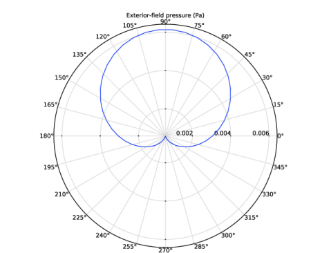
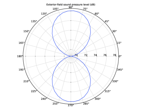
In the Settings window for Polar Plot Group, type Exterior-Field Pressure, xy-Plane in the Label text field.
|
|
1
|
|
2
|
|
3
|
|
4
|
Locate the Evaluation section. Find the Evaluation distance subsection. In the Radius text field, type Rext.
|
|
5
|
|
1
|
|
2
|
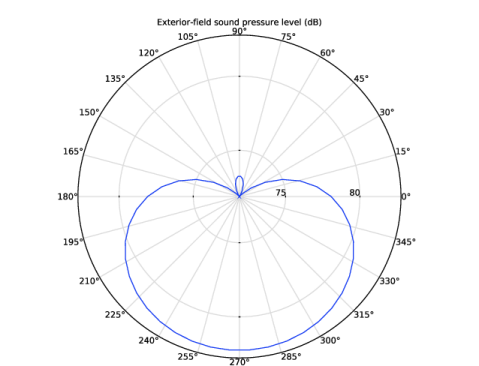
In the Settings window for Polar Plot Group, type Exterior-Field SPL, xy-Plane in the Label text field.
|
|
1
|
In the Model Builder window, expand the Exterior-Field SPL, xy-Plane node, then click Radiation Pattern 1.
|
|
2
|
|
3
|
|
4
|
|
1
|
|
2
|
In the Settings window for Polar Plot Group, type Exterior-Field Pressure, yz-Plane in the Label text field.
|
|
1
|
In the Model Builder window, expand the Exterior-Field Pressure, yz-Plane node, then click Radiation Pattern 1.
|
|
2
|
|
3
|
|
4
|
|
5
|
|
6
|
|
7
|
|
1
|
|
2
|
In the Settings window for Polar Plot Group, type Exterior-Field SPL, yz-Plane in the Label text field.
|
|
1
|
In the Model Builder window, expand the Exterior-Field SPL, yz-Plane node, then click Radiation Pattern 1.
|
|
2
|
|
3
|
|
4
|
|
5
|
|
6
|
|
7
|
|
1
|
|
2
|
Go to the Result Templates window.
|
|
3
|
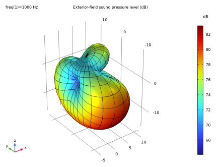
In the tree, select Study 1/Solution 1 (sol1) > Pressure Acoustics, Frequency Domain > Exterior-Field Sound Pressure Level (acpr).
|
|
4
|
Click the Add Result Template button in the window toolbar.
|
|
5
|
|
1
|
|
2
|
|
1
|
In the Model Builder window, expand the Exterior-Field Sound Pressure Level (acpr) node, then click Radiation Pattern 1.
|
|
2
|
|
3
|
|
4
|
|
5
|
|
6
|
|
7
|
|
8
|
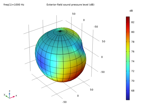
Select the Description checkbox. In the associated text field, type Exterior-field sound pressure level.
|
|
9
|
Clear the Use as color expression checkbox.
|
|
10
|
|
1
|
|
2
|
|
3
|
|
4
|
|
5
|
|
6
|
|
7
|
|
8
|
|
9
|
|
10
|
|
1
|
|
2
|
|
3
|
|
4
|
|
1
|
|
2
|
|
3
|
|
4
|
|
5
|
|
6
|
|
1
|
|
2
|
|
3
|
|
4
|