|
|
|


|
•
|


|
•
|
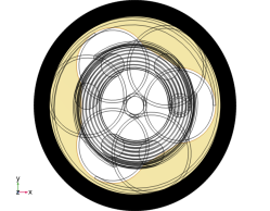
Building the mesh is fast, because it only needs to extrude an already existing surface mesh, using a simple, well-defined projection (assuming the geometry supports it).
|
|
•
|
It is reliable because the procedure is simple and well-determined: The 3D meshing problem is basically reduced to an in-plane 2D mesh, combined with an out-of-plane 1D mesh. The swept mesh will not be sensitive to minor geometric changes.
|
|
•
|
It is efficient in the sense that it allows for highly anisotropic meshes (for which the aspect ratio can be fine-tuned easily), and because the extruded elements — prisms and hexahedra — produce less degrees of freedom per unit volume than pyramids and tetrahedra do. So it is an effective tool for reducing the DOF count.
|

|
•
|
|
1
|
|
2
|
Click Done.
|
|
1
|
|
2
|
Browse to a suitable folder and type the filename submarine_cable_07_a_geom_mesh_3d.mph.
|
|
1
|
|
2
|
|
3
|
|
4
|
Browse to the model’s Application Libraries folder and double-click the file submarine_cable_a_geom_parameters.txt.
|
|
1
|
|
2
|
|
3
|
|
4
|
Browse to the model’s Application Libraries folder and double-click the file submarine_cable_b_geom_parameters.txt.
|
|
1
|
|
2
|
|
3
|
|
4
|
Browse to the model’s Application Libraries folder and double-click the file submarine_cable_f_geom_parameters.txt.
|
|
1
|
|
2
|
|
3
|
|
4
|
|
5
|
|
6
|
Click to expand the Layers section. In the table, enter the following settings:
|
|
7
|
Click
|
|
8
|
|
9
|
|
10
|
|
11
|
|
12
|
|
1
|
|
2
|
|
3
|
|
4
|
|
1
|
|
2
|
|
3
|
|
4
|
|
5
|
|
1
|
|
2
|
|
3
|
|
4
|
|
5
|
|
1
|
|
2
|
|
3
|
|
4
|
|
5
|
Select the Lock camera checkbox.
|
|
1
|
|
2
|
|
3
|
|
4
|
|
5
|
|
6
|
Select the Lock camera checkbox.
|
|
1
|
|
2
|
|
3
|
|
4
|
Clear the Lock camera checkbox.
|
|
5
|
|
6
|
Clear the Show grid checkbox.
|
|
7
|
Select the Lock camera checkbox.
|
|
1
|
|
2
|
|
1
|
|
2
|
|
3
|
|
4
|
|
5
|
|
6
|
|
7
|
|
8
|
|
9
|
|
10
|
|
11
|
|
12
|
|
13
|
|
14
|
|
15
|
|
16
|
|
17
|
|
18
|
|
1
|
|
2
|
|
3
|
|
1
|
|
2
|
|
3
|
|
4
|
In the Settings window for Geometry, in the Graphics window toolbar, click
 |
|
5
|
In the Graphics window toolbar, click
 |
|
6
|
In the Graphics window toolbar, click
 |
|
7
|
In the Graphics window toolbar, click
|
|
1
|
In the Model Builder window, under Component 1 (comp1) > Definitions > View 5 (Perspective) click Camera.
|
|
2
|
|
1
|
|
2
|
Browse to the model’s Application Libraries folder and double-click the file submarine_cable_07_a_geom_mesh_3d.mph.
|
|
3
|
|
4
|
Browse to a suitable folder and type the filename submarine_cable_07_b_geom_mesh_3d.mph.
|
|
1
|
|
2
|
|
3
|
|
1
|
|
2
|
|
3
|
|
4
|
Browse to the model’s Application Libraries folder and double-click the file submarine_cable_c_elec_parameters.txt.
|
|
1
|
|
2
|
|
3
|
|
4
|
|
1
|
In the Model Builder window, under Component 1 (comp1) > Geometry 1, Ctrl-click to select Cylinder 1 (cyl1) and Block 1 (blk1).
|
|
2
|
Right-click and choose Delete.
|
|
1
|
|
2
|
|
3
|
|
4
|
|
5
|
|
6
|
|
7
|
|
1
|
|
2
|
|
3
|
|
4
|
|
5
|
|
1
|
|
2
|
|
3
|
|
4
|
Locate the Selections of Resulting Entities section. Select the Resulting objects selection checkbox.
|
|
5
|
|
1
|
|
2
|
|
1
|
|
2
|
|
3
|
|
4
|
|
5
|
|
6
|
|
1
|
|
2
|
|
3
|
|
4
|
|
5
|
|
6
|
Click to expand the Layers section. In the table, enter the following settings:
|
|
7
|
|
1
|
|
2
|
|
3
|
|
4
|
|
5
|
|
1
|
|
2
|
|
3
|
|
4
|
|
5
|
|
6
|
|
7
|
|
8
|
|
9
|
|
10
|
|
1
|
|
2
|
|
3
|
|
4
|
|
5
|
|
1
|
|
2
|
|
3
|
|
4
|
|
5
|
|
6
|
|
1
|
|
2
|
|
3
|
|
4
|
|
5
|
|
1
|
|
2
|
|
3
|
|
1
|
|
2
|
|
3
|
|
1
|
|
2
|
|
3
|
|
4
|
Locate the Selections of Resulting Entities section. Select the Resulting objects selection checkbox.
|
|
5
|
|
1
|
|
2
|
|
1
|
|
2
|
|
3
|
|
4
|
|
5
|
|
6
|
|
7
|
|
1
|
|
2
|
|
3
|
|
4
|
|
5
|
|
6
|
|
1
|
|
2
|
|
3
|
|
4
|
|
5
|
|
6
|
|
1
|
|
2
|
|
3
|
|
4
|
|
5
|
|
6
|
|
1
|
|
2
|
|
3
|
|
4
|
|
5
|
|
6
|
|
7
|
|
1
|
Right-click Component 1 (comp1) > Geometry 1 > Cable Armor and Sea Bed (wp2) > Plane Geometry > Polygon 3 (pol3) and choose Duplicate.
|
|
2
|
|
3
|
In the xw and yw text fields, update the expression. Type ...*(Darm/2+2*Tarm/3), that is; replace “-2*Tarm/3” with “+2*Tarm/3” to increase the radius.
|
|
4
|
|
1
|
|
2
|
|
3
|
|
4
|
|
5
|
|
6
|
|
1
|
|
2
|
|
3
|
|
4
|
Click
|
|
5
|
|
1
|
In the Model Builder window, under Component 1 (comp1) > Geometry 1 click Cable Armor and Sea Bed (wp2).
|
|
2
|
|
3
|
|
1
|
|
2
|
|
3
|
|
1
|
|
2
|
|
3
|
|
1
|
|
2
|
|
3
|
|
4
|
|
5
|
|
6
|
|
7
|
|
1
|
|
2
|
|
3
|
|
4
|
|
5
|
|
6
|
|
1
|
|
2
|
|
3
|
|
4
|
|
5
|
|
6
|
|
1
|
|
2
|
|
3
|
|
4
|
|
5
|
|
6
|
|
1
|
|
2
|
|
3
|
|
4
|
|
5
|
In the xw text field, type Dpha/sqrt(3)+cos(360[deg]*range(1/20,1/20,1))*(TCFp20*Dcon/2-Dscup*9/16).
|
|
6
|
|
7
|
|
1
|
|
2
|
|
3
|
|
4
|
|
5
|
|
6
|
|
1
|
|
2
|
|
3
|
|
4
|
|
1
|
|
2
|
|
3
|
|
4
|
|
5
|
|
6
|
Locate the Selections of Resulting Entities section. Select the Resulting objects selection checkbox.
|
|
7
|
|
8
|
|
1
|
|
2
|
|
3
|
|
4
|
|
5
|
|
6
|
|
1
|
|
2
|
|
3
|
|
4
|
|
5
|
|
1
|
|
2
|
|
3
|
|
4
|
|
5
|
|
6
|
|
1
|
|
2
|
|
3
|
|
4
|
|
5
|
|
6
|
|
1
|
|
2
|
|
3
|
|
4
|
|
5
|
|
6
|
Click
|
|
7
|
|
8
|
|
1
|
|
2
|
|
3
|
|
4
|
|
5
|
|
6
|
|
7
|
|
1
|
|
2
|
|
3
|
|
4
|
|
5
|
|
6
|
|
1
|
|
2
|
|
3
|
|
1
|
|
2
|
|
3
|
|
4
|
|
5
|
|
6
|
|
1
|
|
2
|
|
3
|
|
4
|
|
5
|
|
6
|
|
1
|
|
2
|
|
3
|
|
4
|
|
5
|
|
6
|
|
7
|
Locate the Selections of Resulting Entities section. Select the Resulting objects selection checkbox.
|
|
8
|
|
9
|
|
1
|
|
2
|
|
3
|
|
4
|
|
5
|
|
6
|
|
1
|
In the Model Builder window, under Component 1 (comp1) > Geometry 1 click Mesh Control Entities (wp3).
|
|
2
|
|
3
|
|
1
|
|
2
|
|
3
|
|
4
|
|
5
|
|
6
|
|
7
|
Locate the Selections of Resulting Entities section. Select the Resulting objects selection checkbox.
|
|
8
|
|
9
|
|
1
|
|
2
|
|
3
|
|
4
|
Locate the Spine Curve section. Click to select the
|
|
5
|
|
6
|
|
7
|
Locate the Motion of Cross Section section. Find the Additional twisting and scaling subsection. In the Twist angle text field, type 360[deg]*Tenab*s[m]/LLpha.
|
|
8
|
|
1
|
In the Model Builder window, under Component 1 (comp1) > Geometry 1 right-click Polygon 2 (pol2) and choose Duplicate.
|
|
2
|
|
1
|
In the Model Builder window, under Component 1 (comp1) > Geometry 1 right-click Sweep 1 (swe1) and choose Duplicate.
|
|
2
|
|
3
|
|
4
|
|
5
|
Locate the Spine Curve section. Click to select the
|
|
6
|
|
7
|
|
8
|
|
9
|
|
1
|
|
2
|
|
3
|
|
•
|
The value of Nper will become an integer, causing the parameter Tenab (defined as round(Nper)==Nper) to become “1” (true).
|
|
•
|
The length of the cable section included in the model Lsec (defined as CPcab*Nper) will increase tenfold. This sets the length of the geometry to be precisely one times the cable’s cross pitch (for more on this, see the Inductive Effects 3D tutorial).
|
|
•
|
The new parameter value Tenab will force the twist angle of the cable section Tsec (defined as 360[deg]*Tenab*Lsec/LLpha) to become “Lsec/LLpha” times one full revolution.
|
|
•
|
In addition to this, Tenab will enable the slant correction factors SCFpha, and SCFarm, and will cause the two sweep operations in the geometry to generate helices instead of straight extrusions.
|
|
1
|
|
2
|
|
3
|
In the Graphics window toolbar, click
 |
|
4
|
In the Graphics window toolbar, click
 |
|
1
|
|
2
|
|
1
|
|
2
|
|
3
|
|
4
|
|
5
|
|
6
|
|
7
|
Clear the Automatic detection of small details checkbox.
|
|
8
|
In the Graphics window toolbar, click
 |
|
1
|
|
2
|
Browse to the model’s Application Libraries folder and double-click the file submarine_cable_07_b_geom_mesh_3d.mph.
|
|
3
|
|
4
|
Browse to a suitable folder and type the filename submarine_cable_07_c_geom_mesh_3d.mph.
|
|
1
|
|
2
|
|
3
|
|
4
|
|
5
|
|
6
|
|
7
|
|
8
|
Locate the Output Entities section. From the Include entity if list, choose All vertices inside cylinder.
|
|
9
|
In the Graphics window toolbar, click
|
|
10
|
|
11
|
In the Graphics window toolbar, click
|
|
12
|
|
1
|
|
2
|
|
3
|
|
1
|
|
2
|
|
3
|
|
4
|
|
5
|
In the Add dialog, in the Selections to add list, choose Cross Section, Top and Cross Section, Bottom.
|
|
6
|
Click OK.
|
|
7
|
In the Settings window for Union, in the Graphics window toolbar, click
|
|
8
|
|
1
|
|
2
|
|
3
|
Locate the Size and Shape section. In the Outer radius text field, type Dpha/sqrt(3)+(Dcon/2+Dins/2)/2.
|
|
4
|
|
5
|
Locate the Output Entities section. From the Include entity if list, choose All vertices inside cylinder.
|
|
6
|
In the Graphics window toolbar, click
 |
|
1
|
|
2
|
|
3
|
|
4
|
|
5
|
|
6
|
Click OK.
|
|
7
|
|
8
|
|
9
|
|
10
|
|
11
|
|
12
|
Locate the Output Entities section. From the Include entity if list, choose Some vertex inside ball.
|
|
13
|
In the Graphics window toolbar, click
 |
|
14
|
In the Graphics window toolbar, click
 |
|
1
|
|
2
|
|
3
|
|
4
|
|
1
|
|
2
|
|
3
|
|
4
|
|
1
|
|
2
|
|
3
|
|
4
|
|
5
|
Click OK.
|
|
6
|
|
7
|
|
8
|
|
1
|
|
2
|
|
3
|
|
4
|
|
5
|
Click OK.
|
|
6
|
|
7
|
|
8
|
|
1
|
|
2
|
|
3
|
|
4
|
|
5
|
Click OK.
|
|
6
|
|
7
|
|
8
|
|
9
|
|
1
|
|
2
|
|
3
|
|
4
|
Select the Group by continuous tangent checkbox.
|
|
5
|
|
6
|
|
7
|
|
8
|
|
9
|
|
10
|
Locate the Output Entities section. From the Include entity if list, choose Some vertex inside cylinder.
 |
|
11
|
In the Graphics window toolbar, click
 |
|
1
|
|
2
|
|
3
|
|
4
|
|
5
|
|
6
|
Click OK.
|
|
7
|
|
8
|
|
9
|
In the Graphics window toolbar, click
 |
|
1
|
|
2
|
|
3
|
|
4
|
|
5
|
|
1
|
|
2
|
|
3
|
|
4
|
|
5
|
|
1
|
|
2
|
|
3
|
|
4
|
Locate the Output Entities section. From the Include entity if list, choose All vertices inside cylinder.
 |
|
1
|
|
2
|
|
3
|
|
4
|
|
5
|
|
6
|
|
1
|
|
2
|
|
3
|
|
4
|
|
5
|
|
1
|
|
2
|
|
3
|
|
4
|
|
5
|
|
1
|
|
2
|
|
3
|
|
4
|
|
5
|
In the Add dialog, in the Selections to intersect list, choose Cross Section, Bottom and Phases, Exterior Boundaries.
|
|
6
|
Click OK.
|
|
7
|
In the Settings window for Intersection, in the Graphics window toolbar, click
 |
|
1
|
|
2
|
In the Settings window for Intersection, type Screens, Boundaries Bottom (Mapped 3) in the Label text field.
|
|
3
|
|
4
|
|
5
|
In the Add dialog, in the Selections to intersect list, choose Cross Section, Bottom and Screens, Exterior Boundaries.
|
|
6
|
|
1
|
|
2
|
|
3
|
|
4
|
|
5
|
In the Add dialog, in the Selections to intersect list, choose Cross Section, Bottom and Armor, Exterior Boundaries.
|
|
6
|
|
1
|
|
2
|
|
3
|
|
4
|
|
5
|
|
6
|
|
7
|
Click OK.
|
|
8
|
|
9
|
|
10
|
|
11
|
Locate the Output Entities section. From the Include entity if list, choose All vertices inside cylinder.
 |
|
1
|
|
2
|
|
3
|
|
4
|
|
1
|
|
2
|
|
3
|
|
4
|
|
5
|
|
6
|
|
1
|
|
2
|
In the Settings window for Difference, type Copy Face 1, Destination Boundaries in the Label text field.
|
|
3
|
|
4
|
|
5
|
|
6
|
Click OK.
|
|
7
|
|
8
|
|
9
|
|
10
|
|
1
|
|
2
|
|
3
|
|
4
|
|
5
|
|
6
|
|
1
|
|
2
|
|
3
|
|
4
|
|
1
|
|
2
|
|
3
|
|
4
|
|
5
|
|
6
|
|
1
|
|
2
|
In the Settings window for Difference, type Copy Face 2, Destination Boundaries in the Label text field.
|
|
3
|
|
4
|
|
5
|
|
6
|
Click OK.
|
|
7
|
|
8
|
|
9
|
|
10
|
Click OK.
|
|
11
|
|
1
|
|
2
|
|
3
|
|
4
|
|
5
|
|
6
|
Click OK.
|
|
7
|
|
8
|
|
9
|
|
10
|
|
1
|
|
2
|
|
3
|
|
4
|
|
5
|
|
6
|
|
7
|
Click OK.
|
|
8
|
|
9
|
|
10
|
|
11
|
Locate the Output Entities section. From the Include entity if list, choose All vertices inside cylinder.
 |
|
12
|
|
1
|
|
2
|
|
3
|
|
4
|
|
5
|
|
6
|
Click OK.
|
|
7
|
|
8
|
|
9
|
In the Add dialog, in the Selections to subtract list, choose Phases, Boundaries Bottom, Screens, Boundaries Bottom (Mapped 3), Armor, Boundaries Bottom, and Mapped 4.
|
|
10
|
|
1
|
|
2
|
|
3
|
|
4
|
|
5
|
|
6
|
|
7
|
Click OK.
|
|
8
|
|
9
|
|
10
|
|
11
|
Locate the Output Entities section. From the Include entity if list, choose All vertices inside cylinder.
 |
|
1
|
|
2
|
|
3
|
|
4
|
Locate the Output Entities section. From the Include entity if list, choose All vertices inside cylinder.
|
|
5
|
|
1
|
|
2
|
|
3
|
|
4
|
|
5
|
|
1
|
|
2
|
|
3
|
|
4
|
In the Add dialog, in the Selections to add list, choose Swept 1, Distribution 1 and Swept 1, Distribution 2.
|
|
5
|
|
6
|
In the Settings window for Union, in the Graphics window toolbar, click
 |
|
1
|
|
2
|
In the Settings window for Complement, type Remaining Domains (Free Tetrahedral 1) in the Label text field.
|
|
3
|
|
4
|
|
5
|
|
1
|
|
2
|
In the Settings window for Adjacent, type Remaining Domains, Exterior Boundaries in the Label text field.
|
|
3
|
|
4
|
|
5
|
|
1
|
|
2
|
|
3
|
|
4
|
|
5
|
|
6
|
Click OK.
|
|
7
|
|
8
|
|
9
|
|
10
|
Click OK.
|
|
11
|
|
12
|
|
1
|
|
2
|
In the Settings window for Intersection, type Copy Face 3, Source Boundaries in the Label text field.
|
|
3
|
|
4
|
|
5
|
In the Add dialog, in the Selections to intersect list, choose Cross Section, Bottom and Remaining Domains, Exterior Boundaries.
|
|
6
|
|
1
|
|
2
|
In the Settings window for Intersection, type Copy Face 3, Destination Boundaries in the Label text field.
|
|
3
|
|
4
|
|
5
|
In the Add dialog, in the Selections to intersect list, choose Cross Section, Top and Remaining Domains, Exterior Boundaries.
|
|
6
|
|
7
|
|
8
|
|
1
|
|
2
|
|
3
|
|
4
|
|
5
|
|
6
|
|
7
|
Click OK.
|
|
8
|
|
9
|
|
10
|
Locate the Output Entities section. From the Include entity if list, choose All vertices inside cylinder.
 |
|
11
|
|
1
|
|
2
|
|
3
|
|
1
|
|
2
|
|
3
|
|
4
|
|
5
|
|
6
|
|
1
|
|
2
|
|
1
|
|
2
|
Browse to the model’s Application Libraries folder and double-click the file submarine_cable_07_c_geom_mesh_3d.mph.
|
|
3
|
|
4
|
Browse to a suitable folder and type the filename submarine_cable_07_geom_mesh_3d.mph.
|
|
1
|
|
2
|
|
3
|
|
4
|
In the Graphics window toolbar, click
|
|
5
|
|
1
|
|
2
|
|
3
|
Click the Custom button.
|
|
4
|
Locate the Element Size Parameters section.
|
|
5
|
|
6
|
|
7
|
Click
|
|
8
|
|
1
|
|
2
|
|
3
|
|
4
|
Click
|
|
5
|
|
1
|
|
2
|
|
3
|
|
4
|
|
5
|
|
6
|
|
1
|
|
2
|
|
3
|
|
4
|
|
1
|
|
2
|
|
3
|
Click the Custom button.
|
|
4
|
Locate the Element Size Parameters section.
|
|
5
|
|
6
|
|
7
|
Click
|
|
8
|
|
9
|
|
1
|
|
2
|
|
3
|
|
4
|
Click
|
|
5
|
|
1
|
|
2
|
|
3
|
|
4
|
|
5
|
|
6
|
|
1
|
|
2
|
|
3
|
|
1
|
|
2
|
|
3
|
Click the Custom button.
|
|
4
|
Locate the Element Size Parameters section.
|
|
5
|
|
6
|
|
7
|
|
1
|
|
2
|
|
3
|
|
1
|
|
2
|
|
3
|
|
4
|
|
5
|
Locate the Element Size Parameters section.
|
|
6
|
|
7
|
|
8
|
|
9
|
|
1
|
|
2
|
|
3
|
|
4
|
|
•
|
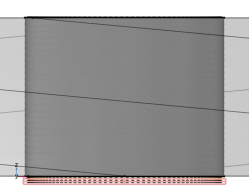
Secondly, it is beneficial for the quality of the tetrahedra. The armor wires and their neighboring domains will be using a structured (swept) mesh, and so will the screens. In-between these domains, an unstructured (free tetrahedral) mesh is used. Every bit of growth that can be squeezed into the first layer of mesh elements close to the armor wires — still within the swept mesh — does not need to be provided by the tetrahedra. This is advantageous since structured meshes are more robust when it comes to rapid growth.
|
|
•
|
Furthermore, it improves the interface between the swept mesh and the tetrahedra. When the swept mesh for the armor is built, a number of out-of-plane elements is generated (the surface mesh is extruded). To limit the DOF count the amount of elements in the direction of extrusion is kept low, so the resulting elements will have a high aspect ratio. Since a large in-plane element size will lower this aspect ratio, and since having a low aspect ratio on the swept-tetrahedral interface is preferable, rapid growth within the swept mesh is needed.
|
|
1
|
|
2
|
|
3
|
|
4
|
|
5
|
|
1
|
|
2
|
|
3
|
|
4
|
|
1
|
|
2
|
|
3
|
|
4
|
|
1
|
|
2
|
In the Settings window for Swept, in the Graphics window toolbar, click
 |
|
1
|
|
2
|
|
3
|
|
4
|
|
5
|
|
1
|
|
2
|
|
3
|
|
4
|
In the Graphics window toolbar, click
 |
|
5
|
|
6
|
|
7
|
In the Graphics window toolbar, click
 |
|
8
|
|
1
|
|
2
|
|
3
|
|
4
|
|
5
|
|
6
|
Click to expand the Element Quality Optimization section. From the Optimization level list, choose High.
|
|
1
|
|
2
|
|
3
|
Click the Custom button.
|
|
4
|
Locate the Element Size Parameters section.
|
|
5
|
|
6
|
Click
|
|
7
|
In the Graphics window toolbar, click
 |
|
8
|
|
9
|
|
1
|
|
1
|
|
2
|
In the Settings window for 3D Plot Group, type Mesh Quality, Volume Elements in the Label text field.
|
|
3
|
|
4
|
|
5
|
|
6
|
Clear the Plot dataset edges checkbox.
|
|
7
|
|
1
|
|
2
|
|
3
|
|
4
|
|
5
|
|
6
|
|
7
|
|
1
|
|
2
|
In the Settings window for 3D Plot Group, type Mesh Quality, Poor Quality Elements in the Label text field.
|
|
3
|
|
1
|
In the Model Builder window, expand the Mesh Quality, Poor Quality Elements node, then click Mesh 1.
|
|
2
|
|
3
|
|
4
|
|
1
|
|
2
|
|
3
|
|
4
|
|
5
|
|
1
|
|
2
|
|
3
|
|
4
|
|
1
|
|
2
|
|
3
|
Click to select the
|
|
4
|
|
5
|
|
1
|
|
2
|
|
3
|
|
4
|
|
5
|
|
6
|
|
7
|
|
8
|
|
1
|
|
2
|
|
3
|
|
4
|
|
5
|
Click
|
|
6
|
In the Graphics window toolbar, click
|
|
7
|
|
1
|
|
2
|
|
3
|
|
4
|
|
5
|
|
1
|
|
2
|
In the Settings window for 2D Plot Group, type Mesh Comparison, Source and Destination in the Label text field.
|
|
3
|
|
4
|
|
1
|
|
2
|
|
3
|
|
4
|
|
5
|
Select the Wireframe checkbox.
|
|
6
|
|
1
|
|
2
|
|
3
|
|
4
|
|
5
|
|
6
|
|
1
|
|
2
|
|
3
|
|
4
|
|
5
|
Locate the Scale section.
|
|
6
|
|
7
|