|
|
|
|
•
|
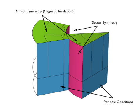
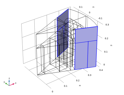
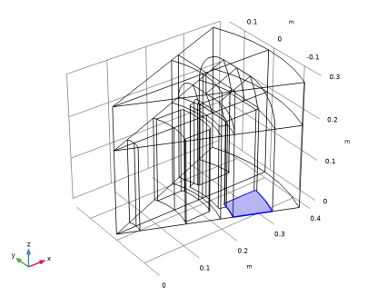
Periodic Conditions must be used on the sides of the sector. The type of periodicity chosen is Antiperiodicity, since the inputs to the model (the remanent flux density in the permanent magnets) change sign in adjacent sectors.
|
|
•
|
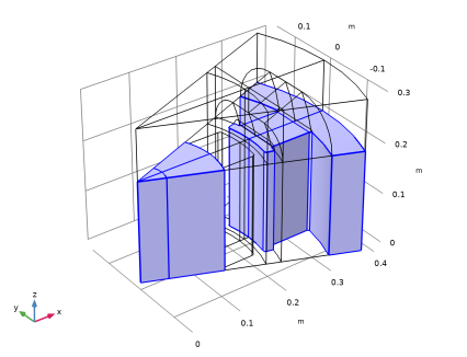
The Sector Symmetry pair condition is applied on the identity pair created by the geometry at the contact boundary between rotor and stator. The type of periodicity must match the type specified in the Periodic Boundary Condition features, that is, Antiperiodicity.
|
|
•
|


|
1
|
|
2
|
In the Select Physics tree, select AC/DC > Electromagnetics and Mechanics > Rotating Machinery, Magnetic (rmm).
|
|
3
|
Click Add.
|
|
4
|
Click
|
|
5
|
In the Select Study tree, select Preset Studies for Selected Physics Interfaces > Coil Geometry Analysis.
|
|
6
|
Click
|
|
1
|
|
2
|
|
1
|
|
2
|
Browse to the model’s Application Libraries folder and double-click the file sector_generator_3d_geom_sequence.mph.
|
|
3
|
|
4
|
|
5
|
|
6
|
|
7
|
Clear the Automatic detection of small details checkbox.
|
|
1
|
|
1
|
|
2
|
|
3
|
|
4
|
|
5
|
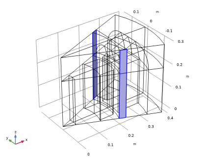
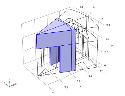
In the Paste Selection dialog, type 17 19 20 22 23 24 in the Selection text field (the domains belonging to the coil).
|
|
6
|
|
1
|
|
2
|
|
1
|
|
2
|
|
1
|
|
2
|
|
3
|
|
4
|
|
5
|
Click OK.
|
|
1
|
|
2
|
|
3
|
|
1
|
|
2
|
In the Settings window for Explicit, type Periodic Condition: Stator, Scalar Potential in the Label text field.
|
|
3
|
|
1
|
|
2
|
In the Settings window for Explicit, type Periodic Condition: Stator, Vector Potential in the Label text field.
|
|
3
|
|
1
|
|
2
|
|
3
|
|
1
|
|
2
|
|
3
|
|
1
|
|
2
|
Go to the Add Material window.
|
|
3
|
|
4
|
Right-click and choose Add to Component 1 (comp1).
|
|
5
|
|
6
|
Right-click and choose Add to Component 1 (comp1).
|
|
7
|
In the tree, select AC/DC > Hard Magnetic Materials > Sintered NdFeB Grades (Chinese Standard) > N50 (Sintered NdFeB).
|
|
8
|
Click the Add to Component button in the window toolbar.
|
|
9
|
|
1
|
|
2
|
|
3
|
|
1
|
|
2
|
In the Settings window for Magnetic Flux Conservation, type Magnetic Flux Conservation: Air Gap in the Label text field.
|
|
1
|
|
2
|
In the Settings window for Magnetic Flux Conservation, type Magnetic Flux Conservation: Rotor Iron in the Label text field.
|
|
4
|
|
1
|
|
2
|
|
3
|
|
1
|
|
2
|
|
4
|
|
1
|
|
2
|
|
3
|
|
1
|
|
2
|
|
3
|
|
4
|
Locate the Constitutive Relation Jc-E section. From the Constrain for induced currents list, choose No induced currents constrain.
|
|
1
|
|
1
|
|
1
|
|
2
|
|
3
|
|
4
|
|
5
|
|
6
|
|
7
|
|
8
|
|
1
|
|
2
|
|
3
|
|
1
|
|
1
|
|
1
|
|
2
|
|
3
|
Click
|
|
4
|
|
5
|
Click OK.
|
|
6
|
|
7
|
|
8
|
|
1
|
|
2
|
|
3
|
|
4
|
|
1
|
|
2
|
|
3
|
|
4
|
|
1
|
|
2
|
|
3
|
|
4
|
|
1
|
|
2
|
|
3
|
|
4
|
|
5
|
|
6
|
|
1
|
|
2
|
|
1
|
|
2
|
|
1
|
|
2
|
|
3
|
|
5
|
|
1
|
|
2
|
|
3
|
|
1
|
|
2
|
|
3
|
|
4
|
|
5
|
|
6
|
|
7
|
|
1
|
|
3
|
|
4
|
Click to select the
|
|
6
|
|
1
|
|
2
|
|
3
|
|
4
|
Locate the Physics and Variables Selection section. Select the Modify model configuration for study step checkbox.
|
|
5
|
In the tree, select Component 1 (comp1) > Rotating Machinery, Magnetic (rmm), Controls spatial frame > Gauge Fixing for A-Field 1.
|
|
6
|
Right-click and choose Disable.
|
|
1
|
|
2
|
|
3
|
|
1
|
|
2
|
|
3
|
|
4
|
Click to expand the Advanced section. Find the Space variables subsection. Select the Invert phase when rotating checkbox.
|
|
1
|
|
2
|
|
3
|
|
4
|
|
1
|
|
2
|
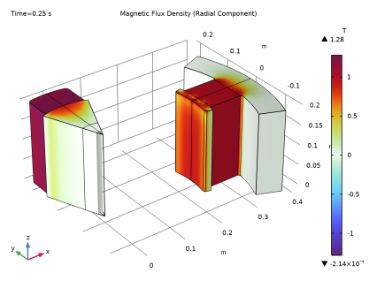
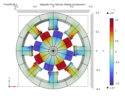
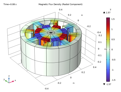
In the Settings window for 3D Plot Group, type Magnetic Flux Density (Radial Component) in the Label text field.
|
|
3
|
|
4
|
|
5
|
|
6
|
|
7
|
Select the Show units checkbox.
|
|
1
|
|
2
|
In the Settings window for Volume, click Replace Expression in the upper-right corner of the Expression section. From the menu, choose Component 1 (comp1) > Definitions > Cylindrical System 2 > Base vector (sys2) r (spatial frame) > sys2.e_r1 - Base vector (sys2) r, x-component.
|
|
3
|
Locate the Expression section. In the Expression text field, type sys2.e_r1*rmm.Bx+sys2.e_r2*rmm.By.
|
|
4
|
Select the Description checkbox. In the associated text field, type Magnetic flux density, r component.
|
|
5
|
|
6
|
|
1
|
|
2
|
|
3
|
Select the Plot checkbox.
|
|
4
|
|
5
|
|
6
|
|
7
|
Clear the Generate default plots checkbox.
|
|
8
|
|
1
|
|
2
|
|
3
|
|
4
|
|
5
|
|
6
|
|
7
|
|
8
|
|
9
|
|
1
|
|
2
|
|
1
|
|
2
|
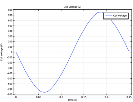
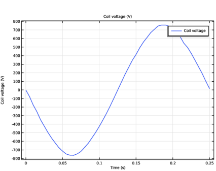
In the Settings window for Global, click Replace Expression in the upper-right corner of the y-Axis Data section. From the menu, choose Component 1 (comp1) > Rotating Machinery, Magnetic (Magnetic Fields) > Coil parameters > rmm.VCoil_1 - Coil voltage - V.
|
|
3
|
|
1
|
|
2
|
Go to the Add Study window.
|
|
3
|
Find the Studies subsection. In the Select Study tree, select Preset Studies for Selected Physics Interfaces > Time-to-Frequency Losses.
|
|
4
|
Click the Add Study button in the window toolbar.
|
|
5
|
|
1
|
|
2
|
|
3
|
|
4
|
|
1
|
|
2
|
|
3
|
|
5
|
Locate the Expressions section. In the table, enter the following settings:
|
|
6
|
Click
|
|
1
|
|
2
|
|
3
|
|
4
|
|
5
|
|
6
|