|
|
|
|
1
|
|
2
|
|
3
|
Click Add.
|
|
4
|
Click
|
|
5
|
|
6
|
Click
|
|
1
|
|
2
|
|
1
|
|
2
|
|
3
|
|
4
|
|
5
|
Click to expand the Layers section. In the table, enter the following settings:
|
|
1
|
|
2
|
On the object pt1, select Point 1 only.
|
|
3
|
|
4
|
|
5
|
On the object c1, select Point 7 only.
|
|
6
|
|
1
|
|
3
|
|
4
|
|
1
|
|
2
|
|
3
|
|
4
|
|
5
|
Click to expand the Layers section. In the table, enter the following settings:
|
|
6
|
Select the Layers to the left checkbox.
|
|
7
|
Clear the Layers on bottom checkbox.
|
|
8
|
|
9
|
|
1
|
|
2
|
Go to the Add Physics window.
|
|
3
|
In the tree, select AC/DC > Electromagnetic Fields > Vector Formulations > Magnetic and Electric Fields (mef).
|
|
4
|
Click the Add to Component 2 button in the window toolbar.
|
|
5
|
|
1
|
|
2
|
|
1
|
|
3
|
|
4
|
|
1
|
|
1
|
|
1
|
|
2
|
|
3
|
In the Solve for column of the table, under Component 2 (comp2), clear the checkbox for Magnetic and Electric Fields (mef).
|
|
1
|
|
2
|
Go to the Add Material window.
|
|
3
|
|
4
|
Click the Add to Component button in the window toolbar.
|
|
5
|
|
1
|
In the Model Builder window, under Component 2 (comp2) > Materials right-click Air (mat1) and choose Duplicate.
|
|
2
|
|
4
|
Locate the Material Contents section. In the table, enter the following settings:
|
|
1
|
|
2
|
Go to the Add Study window.
|
|
3
|
|
4
|
Click the Add Study button in the window toolbar.
|
|
5
|
|
1
|
|
2
|
In the Solve for column of the table, under Component 1 (comp1), clear the checkbox for Magnetic Fields (mf).
|
|
3
|
|
1
|
|
2
|
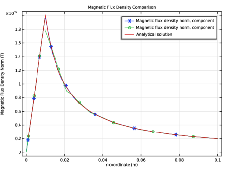
In the Settings window for 1D Plot Group, type Magnetic Flux Density Comparison in the Label text field.
|
|
3
|
|
4
|
|
1
|
|
2
|
|
3
|
|
5
|
|
6
|
|
7
|
|
8
|
|
9
|
Select the Description checkbox.
|
|
10
|
|
11
|
Click to expand the Coloring and Style section. Find the Line markers subsection. From the Marker list, choose Cycle.
|
|
12
|
|
1
|
|
2
|
|
3
|
|
4
|
Select the y-axis label checkbox. In the associated text field, type Magnetic Flux Density Norm (T).
|
|
1
|
|
2
|
|
3
|
|
5
|
|
6
|
|
7
|
|
8
|
|
9
|
|
10
|
Select the Description checkbox.
|
|
11
|
|
12
|
Locate the Coloring and Style section. Find the Line markers subsection. From the Marker list, choose Cycle.
|
|
13
|
|
1
|
|
2
|
|
3
|
|
5
|
Locate the y-Axis Data section. In the Expression text field, type mu0_const*J0/2*r*(r<=ri)+mu0_const*I0/(2*pi*r)*(r>ri).
|
|
6
|
|
7
|
|
8
|
Select the Expression checkbox.
|
|
9
|
|
11
|
|
12
|
|
1
|
|
2
|
In the Settings window for 3D Plot Group, type Air Domain Return Current (mef) in the Label text field.
|
|
1
|
|
2
|
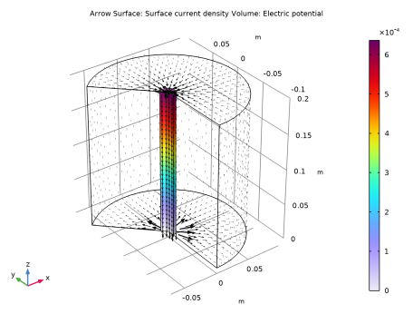
In the Settings window for Arrow Surface, click Replace Expression in the upper-right corner of the Expression section. From the menu, choose Component 2 (comp2) > Magnetic and Electric Fields > Currents and charge > mef.Jsr,...,mef.Jsz - Surface current density.
|
|
3
|
|
4
|
Locate the Coloring and Style section.
|
|
5
|
|
6
|
|
7
|
|
1
|
|
2
|
|
3
|
|
4
|
|
5
|
|
6
|
|
7
|
Locate the Coloring and Style section.
|
|
8
|
|
9
|
|
10
|
|
1
|
|
3
|
|
1
|
|
2
|
|
3
|
|
4
|
|
5
|
|
6
|