|
|
|

|
1
|
|
2
|
In the Select Physics tree, select AC/DC > Electric Fields and Currents > Electrostatics, Boundary Elements (esbe).
|
|
3
|
Click Add.
|
|
4
|
Click
|
|
5
|
In the Select Study tree, select Preset Studies for Selected Physics Interfaces > Stationary Source Sweep.
|
|
6
|
Click
|
|
1
|
|
2
|
|
3
|
|
4
|
|
5
|
|
1
|
|
2
|
|
3
|
|
4
|
Click
|
|
1
|
|
2
|
|
3
|
|
4
|
|
5
|
|
1
|
|
2
|
Select the object r1 only.
|
|
3
|
|
4
|
|
5
|
|
6
|
Click
|
|
1
|
|
2
|
|
3
|
|
1
|
|
2
|
Go to the Add Material window.
|
|
3
|
|
4
|
Right-click and choose Add to Component 1 (comp1).
|
|
5
|
|
6
|
Right-click and choose Add to Component 1 (comp1).
|
|
7
|
|
1
|
|
2
|
|
3
|
|
1
|
|
1
|
|
1
|
|
1
|
|
1
|
|
1
|
|
1
|
|
1
|
|
2
|
|
3
|
|
4
|
|
5
|
Click
|
|
1
|
In the Model Builder window, under Component 1 (comp1) click Electrostatics, Boundary Elements (esbe).
|
|
2
|
In the Settings window for Electrostatics, Boundary Elements, click to expand the Discretization section.
|
|
3
|
|
1
|
|
2
|
|
3
|
In the Model Builder window, expand the Study 1 > Solver Configurations > Solution 1 (sol1) > Stationary Solver 1 node.
|
|
4
|
Right-click Study 1 > Solver Configurations > Solution 1 (sol1) > Stationary Solver 1 > Direct and choose Enable.
|
|
5
|
|
1
|
|
2
|
|
1
|
|
2
|
|
3
|
|
4
|
|
5
|
|
1
|
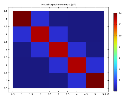
In the Model Builder window, expand the Results > Lumped Parameters (dset1, esbe) > Mutual capacitance (dset1, esbe) node, then click Results > Lumped Parameters (dset1, esbe) > Maxwell capacitance (dset1, esbe) > Maxwell capacitance (dset1, esbe).
|
|
2
|
|
3
|
|
1
|
In the Model Builder window, under Results > Lumped Parameters (dset1, esbe) > Mutual capacitance (dset1, esbe) click Mutual capacitance (dset1, esbe).
|
|
2
|
|
3
|
|
4
|
|
1
|
Go to the Mutual capacitance (dset1, esbe) window.
|
|
2
|
Click the Table Surface button in the window toolbar.
|
|
1
|
|
2
|
|
3
|
|
1
|
|
2
|
|
3
|
|
4
|
|
5
|
|
6
|
|
1
|
|
2
|
|
1
|
|
2
|
|
3
|
|
4
|
|
5
|
|
6
|
|
7
|
|
8
|
|
9
|
|
10
|
Click
|
|
1
|
In the Model Builder window, expand the Component 1 (comp1) > Definitions node, then click Component 1 (comp1) > Deformed Geometry > Prescribed Deformation 1.
|
|
2
|
|
3
|
|
5
|
|
1
|
|
3
|
|
4
|
|
5
|
In the list box, select Finite void 1.
|
|
6
|
Click
|
|
1
|
|
2
|
|
3
|
|
4
|
Click
|
|
1
|
|
2
|
|
3
|
Click
|
|
5
|
|
1
|
|
2
|
|
1
|
|
2
|
|
3
|
Click
|
|
1
|
|
2
|
|
3
|
|
4
|
|
5
|
|
1
|
In the Model Builder window, under Results > Electric Potential (esbe) 1 right-click Streamline Multislice 1 and choose Disable.
|
|
2
|
|
1
|
|
2
|
|
3
|
|
4
|
|
5
|
|
6
|
|
7
|
|
1
|
|
2
|
|
3
|
|
4
|
|
1
|
|
2
|
|
3
|
|
4
|
|
5
|
|
6
|
|
7
|
|
1
|
|
2
|
|
3
|
|
4
|
|
5
|
|
1
|
|
2
|
|
3
|
|
4
|
|
5
|
|
6
|
|
1
|
|
2
|
|
4
|
|
5
|