|
|
|

|
1
|
|
2
|
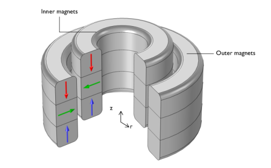
In the Select Physics tree, select AC/DC > Magnetic Fields, No Currents > Magnetic Fields, No Currents (mfnc).
|
|
3
|
Click Add.
|
|
4
|
Click
|
|
5
|
|
6
|
Click
|
|
1
|
|
2
|
|
1
|
|
2
|
|
3
|
|
1
|
|
2
|
|
3
|
|
4
|
|
5
|
|
6
|
|
7
|
Click
|
|
8
|
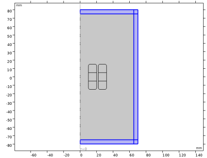
Click to expand the Layers section. In the table, enter the following settings:
|
|
9
|
Select the Layers on top checkbox.
|
|
10
|
Click
|
|
1
|
|
2
|
|
3
|
|
4
|
|
5
|
|
6
|
Click
|
|
1
|
|
2
|
|
3
|
|
4
|
|
5
|
|
6
|
Locate the Layers section. In the table, enter the following settings:
|
|
7
|
Select the Layers to the right checkbox.
|
|
8
|
Select the Layers on top checkbox.
|
|
9
|
Click
|
|
10
|
|
1
|
|
2
|
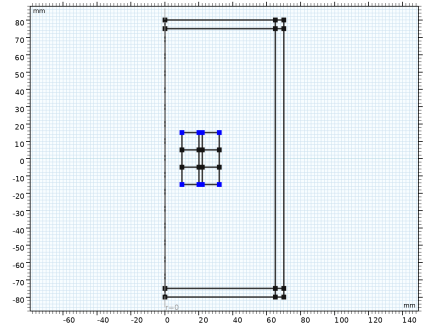
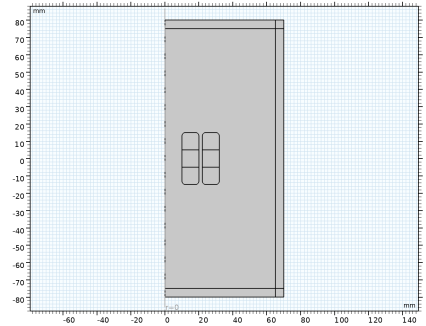
On the object r1, select Points 1, 4, 5, and 8 only.
|
|
3
|
|
4
|
|
5
|
|
6
|
Click
|
|
7
|
|
1
|
|
3
|
|
4
|
|
1
|
|
3
|
In the Settings window for Magnetic Flux Conservation in Solids, locate the Constitutive Relation B-H section.
|
|
4
|
|
5
|
Specify the e vector as
|
|
1
|
|
3
|
In the Settings window for Magnetic Flux Conservation in Solids, locate the Constitutive Relation B-H section.
|
|
4
|
|
5
|
Specify the e vector as
|
|
1
|
|
3
|
In the Settings window for Magnetic Flux Conservation in Solids, locate the Constitutive Relation B-H section.
|
|
4
|
|
1
|
|
3
|
In the Settings window for Magnetic Flux Conservation in Solids, locate the Constitutive Relation B-H section.
|
|
4
|
|
5
|
Specify the e vector as
|
|
1
|
|
2
|
Go to the Add Material window.
|
|
3
|
In the tree, select AC/DC > Hard Magnetic Materials > Sintered NdFeB Grades (Chinese Standard) > N50 (Sintered NdFeB).
|
|
4
|
Right-click and choose Add to Component 1 (comp1).
|
|
5
|
|
2
|
|
4
|
|
1
|
|
3
|
|
4
|
|
1
|
|
2
|
In the Settings window for Force Calculation, type Force Calculation, Object 1 in the Label text field.
|
|
1
|
In the Model Builder window, under Component 1 (comp1) > Magnetic Fields, No Currents (mfnc) click Force Calculation 1.
|
|
2
|
In the Settings window for Force Calculation, type Force Calculation, Object 0 in the Label text field.
|
|
1
|
|
1
|
|
2
|
Go to the Add Physics window.
|
|
3
|
|
4
|
Click the Add to Component 1 button in the window toolbar.
|
|
5
|
|
1
|
|
2
|
|
3
|
In the Control variables table, enter the following settings:
|
|
1
|
|
2
|
|
3
|
|
1
|
|
3
|
|
4
|
|
1
|
|
2
|
|
3
|
|
4
|
Click
|
|
5
|
|
7
|
|
1
|
|
1
|
|
2
|
|
1
|
|
2
|
|
3
|
Click
|
|
4
|
From the list in the Parameter name column choose dZ (Axial displacement), and set the Parameter unit to mm.
|
|
5
|
Click
|
|
6
|
|
7
|
|
8
|
|
9
|
Click Replace.
|
|
10
|
|
11
|
|
12
|
Clear the Generate default plots checkbox.
|
|
1
|
|
2
|
|
3
|
Right-click Study 1 > Solver Configurations > Solution 1 (sol1) > Stationary Solver 1 and choose Sensitivity.
|
|
4
|
|
1
|
|
2
|
|
3
|
|
4
|
|
1
|
|
2
|
|
3
|
|
1
|
|
2
|
|
3
|
|
4
|
|
5
|
|
1
|
|
2
|
In the Settings window for 2D Plot Group, type Magnetic Flux Density, 2D Visualization in the Label text field.
|
|
1
|
|
2
|
In the Settings window for Surface, click Replace Expression in the upper-right corner of the Expression section. From the menu, choose Component 1 (comp1) > Magnetic Fields, No Currents > Magnetic > mfnc.normB - Magnetic flux density norm - T.
|
|
3
|
|
1
|
In the Model Builder window, right-click Magnetic Flux Density, 2D Visualization and choose Streamline.
|
|
2
|
|
3
|
|
4
|
|
5
|
Locate the Coloring and Style section. Find the Point style subsection. From the Color list, choose Gray.
|
|
6
|
|
7
|
|
1
|
|
2
|
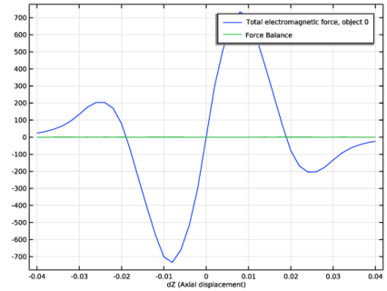
In the Settings window for 1D Plot Group, type Force vs dZ and Force Balance in the Label text field.
|
|
1
|
|
2
|
|
3
|
|
4
|
|
5
|
Click Replace Expression in the upper-right corner of the y-Axis Data section. From the menu, choose Component 1 (comp1) > Sensitivity > sens.gobj1 - Objective value - N.
|
|
6
|
Click Add Expression in the upper-right corner of the y-Axis Data section. From the menu, choose Component 1 (comp1) > Magnetic Fields, No Currents > Mechanical > Total electromagnetic force, object 0 (spatial frame) - N > mfnc.Forcez_0 - Total electromagnetic force, object 0, component z.
|
|
7
|
Locate the y-Axis Data section. In the table, enter the following settings:
|
|
8
|
|
9
|
Click
|
|
1
|
|
2
|
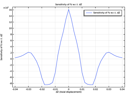
In the Settings window for 1D Plot Group, type Magnetic Stiffness Coefficient in the Label text field.
|
|
1
|
|
2
|
|
3
|
|
4
|
|
6
|
|
1
|
|
2
|
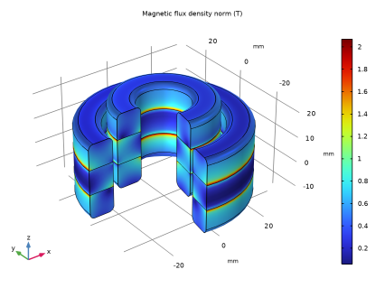
In the Settings window for 3D Plot Group, type Magnetic Fields, Revolution Visualization in the Label text field.
|
|
1
|
|
2
|
In the Settings window for Volume, click Replace Expression in the upper-right corner of the Expression section. From the menu, choose mfnc.normB - Magnetic flux density norm - T.
|
|
3
|