Impeller Parts
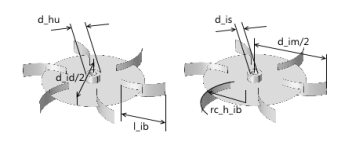
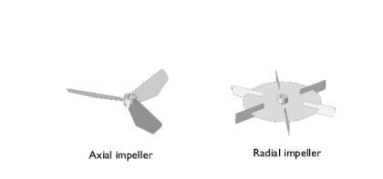
As seen in Figure 2-1, the impeller parts are sorted into three categories, depending on the principal direction of the flow generated by the impeller rotation (axial or radial flow), or if the impeller type is used to mix highly viscous fluids. In total, the Mixer Module Part Library includes eleven impellers: five axial impellers, four radial impellers, and two impellers for highly viscous fluids.
Axial and radial impellers
Axial impellers give the flow an axial component naturally achieving mixing along the z-axis of the mixer. This type of mixers is appropriate for fluids that are sensitive to high shear rates. For example, fermentation processes have living cells in the reactor solution, cells that would be killed by high shear rates. In these processes, axial impellers are often selected and baffles are usually omitted.
Radial impellers force the flow in the radial direction and only give an axial component once the flow hits the walls of the vessel. In order to achieve good mixing, these impellers rely on high shear rates and the presence of baffles, that disrupts tangential flows that would lead to poor mixing.
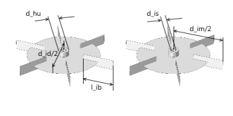
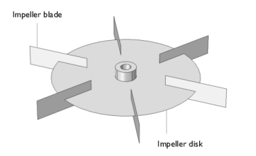
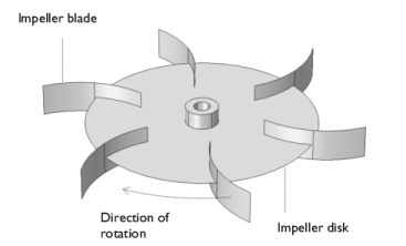
Figure 2-3 below shows an example of an axial and a radial impeller.
Figure 2-3: Examples of an axial impeller (pitched impeller) and a radial impeller (Rushton turbine).
Pitched Blade Impeller
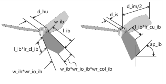
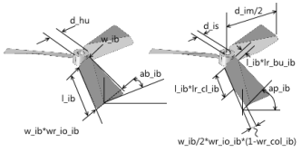
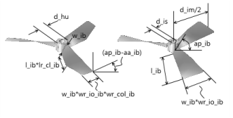
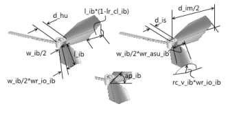
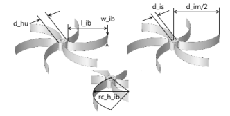
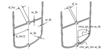
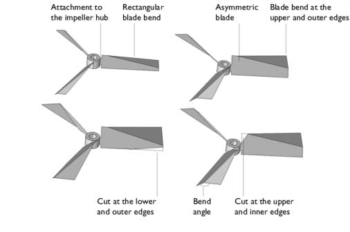
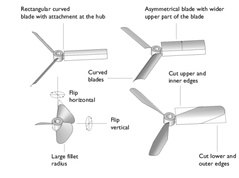
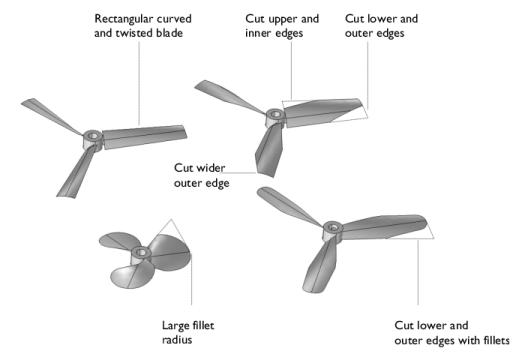
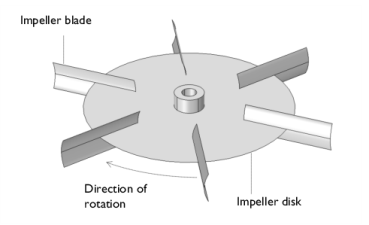
The most common axial impeller is the pitched blade impeller; see Figure 2-4 below. This impeller can be configured for rectangular blades or for isosceles trapezoid-shaped blades. These blade shapes can be created with wider outer or inner edges.
Figure 2-4: Possible configuration of impeller blades for symmetrical blades.
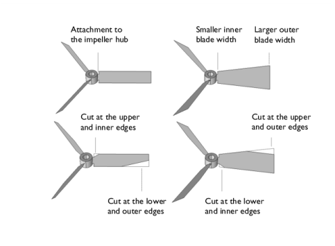
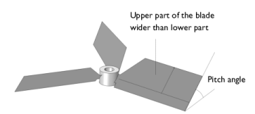
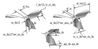
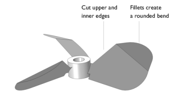
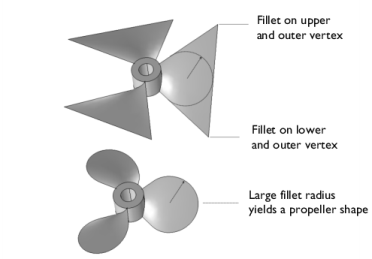
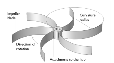
In addition to the symmetrical blades, asymmetrical blades can also be created. In order to create asymmetrical blades, the upper part of the blade is made wider than the lower part (see Figure 2-5). The impeller can then be flipped vertically to have the wider part of the blade facing downward. The pitch angle of the impeller blades can be varied between 0 and 90 degrees. The outer vertices of the outer edges can also be rounded using fillets.
Figure 2-5: Asymmetrical blade. The upper part of the blade is wider than the lower part.
The figure below contains the notations used for the pitched impeller in the part library. The full list of parameters together with their description is found in Table 2-1.
Figure 2-6: Notations used for the pitched impeller.
Pitched Impeller with Bent Blades
Bent blades may be used to decrease the pitch at the outer part (away from the hub) of the impeller blade. Bending these parts gives a less aggressive pitch angle at the outer edges. Using the Mixer Module, the bending is restricted to the upper and outer edges of the impeller blades. The upper part can also be made wider than the lower part to obtain an asymmetrical blade. However, you can flip the impeller vertically to get a bend or wider part that faces downward.
Figure 2-7: Available blade bend and cut operations.
The vertices of the outer vertical edge can be rounded using fillets. The figure below shows an impeller with asymmetrical blades and rounded vertices.
Figure 2-8: Asymmetrical impeller blades with rounded outer (away from the hub) vertices.
The figure below contains the notations used for the pitched impeller with bent blades in the part library. The full list of parameters together with their description is found in Table 2-1
Figure 2-9: Notations used for the pitched impeller with bent blades.
Pitched Blade Impeller with Constant Pitch
For regular pitched impellers, the pitch increases with the radius of the impeller blades, since the blade parts travel with increasing velocity with increasing radius. This means that if the impeller rotated in a fluid, but was allowed to move freely in the axial direction, the outer edge of a regular pitched impeller would want to travel at a higher axial velocity than the inner edge. This effect subjects the impeller blade to a high bending moment. The pitched impeller with constant pitch adapts the pitch angle with the increasing radius so that the outer and inner edges get the same axial velocity as the impeller rotates.
As for the regular pitched impellers, the pitched impeller with constant pitch can be designed with isosceles trapezoid-shaped blade projections (the blades are not flat). The blades can also be cut in both upper and lower edges to achieve different impeller configurations.
Figure 2-10: Pitched impellers with constant pitch with different blade shapes.
The inner pitch angle can be varied in order to change the axial and radial components of the flow induced by the impeller. The pitch angle is then automatically calculated to give a constant pitch.
The outer vertices of the blades can be rounded, which gives additional freedom in the design of the impeller blades. The figure below shows a propeller created by using fillets and cuts and applying those on a pitched impeller with constant pitch.
Figure 2-11: Impeller of propeller type created using isosceles trapezoid-shaped blade projections and large fillet radii for the outer vertices of the blades.
The figure below contains the notations used for the pitched impeller with constant pitch in the part library. The full list of parameters together with their description is found in Table 2-1
Figure 2-12: Notations used for the pitched impeller with constant pitch.
Hydrofoil impeller
Impellers with blades that are curved along the vertical edges are denoted hydrofoil impellers. These impellers are similar to the pitched blade impellers, but give an additional pressure difference across the impeller blade with an additionally lowered pressure on the convex side of the blade.
In addition to varying the curvature radius of the blades, the shape of the impeller blade projections can be varied to get the same freedom in the design of hydrofoil impellers as for the case of the pitched impeller mentioned above. This implies that isosceles trapezoid-shaped blade projections, asymmetrical blades with a wider upper part, and cut blades can be used to create the desired design. Fillets make it possible to create impellers of propeller type.
As in the case for the pitched impeller type, the pitch angle can be varied to control the relation between the radial and axial flow created as the impeller rotates.
Figure 2-13: The curved blades can be shaped to create a large variety of impeller designs.
The figure below contains the notations used for the hydrofoil impeller in the part library. The full list of parameters together with their description is found in Table 2-1
Figure 2-14: Notations used for the hydrofoil impeller.
Hydrofoil Impeller with Constant Pitch
In the same fashion as for the pitched impeller, the hydrofoil impeller creates an axial flow velocity that increases with the impeller radius as the impeller rotates. This effect subjects the impeller blade to a bending moment. A hydrofoil impeller with constant pitch adapts the pitch angle in order to obtain an almost constant pitch of the projection of the curved blade along the radius of the impeller blades. Note that it is not possible (at least not easy) to obtain an exactly constant pitch with increasing radius for the hydrofoil impeller since the blades are curved.
As in the case for the regular hydrofoil impellers, the hydrofoil impeller with constant pitch gives an additional pressure difference across the impeller blade with an additionally lowered pressure on the convex side of the blade.
The impeller blade can be designed with cut blades and asymmetrical blades. Fillets can be used to obtain impellers of propeller type.
Figure 2-15: Hydrofoil impellers with constant pitch.
The figure below contains the notations used for the hydrofoil with constant pitch impeller in the part library. The full list of parameters together with their description is found in Table 2-1
Figure 2-16: Notations used for the hydrofoil with constant pitch.
propeller with constant pitch
A propeller is an axial impeller designed to exert thrust on a fluid in order to propel a boat, or to pump fluid through a duct or a pipe. The pitch angle of the blades can be varied to obtain optimal performance for different working conditions. The figure below contains the notations used for the propeller with constant pitch in the part library. The full list of parameters together with their description is found in Table 2-1.
Figure 2-17: Notations used for the propeller with constant pitch.
The C-Shaped outer Blade Impeller
This is an axial impeller that is suitable for fluids with relatively high viscosity. It consists of two pitched blades equipped with a c-shaped double-blade part that adds shear at the outer radius of the impeller. This impeller can be used to create the so-called Intermig® impeller.
The impeller can be designed with different pitch angles on the arms of the impeller. Also the angles of the c-shaped part can be varied. The profile can be changed by changing the vertical angle of the c-shaped part but keeping the upper and lower blades parallel. In addition, also the angle of the back of the “c” can be varied, keeping the lower and upper blades parallel but displacing them in the xy-plane.
Figure 2-18: The c-shaped with outer blades impeller.
The figure below contains the notations used for the c-shaped outer blade impeller in the part library. The full list of parameters together with their description is found in Table 2-1
Figure 2-19: Notations used for the c-shaped outer blade impeller.
Rushton Turbine
Radial impellers, such as the Rushton turbine, work by pumping the fluid toward the walls of the vessel and then let the collision of the fluid with the wall supply the axial mixing and the turbulence required for mixing. In order to avoid a tangential flows that would result in a poor mixing, baffles are often used in combination with Rushton turbines. Rushton turbines induce a relatively high shear rate and therefore appropriate in processes where the fluid is not sensitive to shear rates.
The turbine can be designed with different blade lengths and also with different disk diameters.
Figure 2-20: The Rushton turbine.
The figure below contains the notations used for the Rushton turbine in the part library. The full list of parameters together with their description is found in Table 2-1
Figure 2-21: Notations used for the Rushton turbine.
The Rushton Turbine with Backswept blades
This type of impeller is similar to the Rushton turbine. The backswept blades allow for a smoother operation with lower shear rates. It is possible to vary the blade length, the disk diameter, as well as the curvature and blade angle relative to the perimeter of the disk.
Figure 2-22: The Rushton turbine with backswept blades.
The figure below contains the notations used for the Rushton turbine with backswept blades in the part library. The full list of parameters together with their description is found in Table 2-1
Figure 2-23: Notations used for the Rushton turbine with backswept blades.
The Smith Turbine
This is also an impeller that resembles the Rushton turbine. It has the same properties as the Rushton turbine but with a somewhat smoother operation with lower shear rates. The length of the blades, the diameter of the disk, as well as the radius of the curvature of the blades can be varied when creating the impeller geometry.
Figure 2-24: The Smith turbine.
The figure below contains the notations used for the Smith turbine in the part library. The full list of parameters together with their description is found in Table 2-1
Figure 2-25: Notations used for the Smith turbine.
The Backswept Blade Impeller
This impeller type is suitable for fluids with low viscosity and density (for example, gases). The curvature of the blades create smooth operating conditions with relatively small shear rates compared to straight blades. The impeller can be designed with different blade lengths and curvatures of the blades.
Figure 2-26: The backswept impeller.
The figure below contains the notations used for the backswept blade impeller in the part library. The full list of parameters together with their description is found in Table 2-1
Figure 2-27: Notations used for the backswept blade impeller.
Anchor Impeller
This impeller type is suitable for mixing fluids of very high viscosity. For example, this impeller is common when mixing Portland concrete and paints in small scales.The lower part of the impeller is shaped as an ellipse that is cut in the middle. The major axis of the ellipse equals the impeller diameter while the minor axis equals to the dished tank where the impeller is placed minus the clearance between the impeller and tank wall.
Figure 2-28: Anchor impeller.
The figure below contains the notations used for the anchor impeller in the part library. The full list of parameters together with their description is found in Table 2-1
Figure 2-29: Notations used for the anchor impeller.