Geometry 1
For many microfluidic devices it is convenient to specify the geometry dimensions using micrometers. Since the device is symmetric, it is only necessary to model half of it.
1
In the Model Builder window, under Component 1 click Geometry 1
.
2
In the Settings window for Geometry, locate the Units section. From the Length unit list, choose
μ
m.
The geometry can be constructed by extruding a 2D work plane. First draw a top down view of the structure in the work plane.
Work Plane 1
1
In the Geometry toolbar, click Work Plane
.
2
In the Settings window for Work Plane, click Go to Plane Geometry
.
3
In the Model Builder window, click Plane Geometry
Rectangle 1
1
Right-click Plane Geometry
and choose Rectangle
2
In the Settings window for Rectangle, locate the Size and Shape section.
-
In the Width text field, type
140
.
-
In the Height text field, type
60
.
3
Click the Build Selected button
.
Rectangle 2
1
Right-click Plane Geometry
and choose Rectangle
.
2
In the Settings window for Rectangle locate the Size and Shape section.
-
In the Width text field, enter
120
.
-
In the Height text field, enter
50
.
3
Locate the Position section.
-
In the xw text field, enter
10
.
-
In the yw text field, enter
10
.
4
Click the Build Selected button
.
Difference 1
1
Right-click Plane Geometry
and choose Booleans and Partitions > Difference
.
2
In the Settings window for Difference, locate the Difference section.
3
In Objects to add, select the object r1 only.
4
In the Settings window for Difference, locate the Difference section. Under Objects to subtract, toggle the Activate Selection button
.
5
Select the object r2 only.
6
Click the Build Selected button
.
Fillet 1
1
Right-click Plane Geometry
and choose Fillet
.
2
On the object dif1, select Points 3 and 5 only.
It might be easier to select the correct points by using the Selection List window. To open this window, in the Home toolbar click Windows and choose Selection List. (If you are running the cross-platform desktop, you find Windows in the main menu). You can also click the Paste Selection button
and enter the information in the Selection text field. For more information about selecting geometric entities in the Graphics window, see the
COMSOL Multiphysics Reference Manual
.
3
In the Settings window for Fillet, locate the Radius section. In the Radius text field, type
10
.
4
Click the Build Selected button
.
Fillet 2
1
Right-click Plane Geometry
and choose Fillet
.
2
On the object fil1, select Points 1 and 9 only.
3
In the Settings window for Fillet locate the Radius section. In the Radius text field, enter
20
.
4
Click the Build Selected button
.
Mirror 1
1
Right-click Plane Geometry
and choose Transforms
> Mirror.
2
Select the object fil2 only.
3
In the Settings window for Mirror, locate the Input section. Select the Keep input objects checkbox.
4
Locate the Normal Vector to Line of Reflection section.
-
In the xw text field, type
0
.
-
In the yw text field, type
1
.
5
Click the Build Selected button
.
Union 1
1
Right-click Plane Geometry
and choose Booleans and Partitions
> Union
.
2
Click in the Graphics window and then press Ctrl+A to select both objects.
3
Click the Build Selected button
.
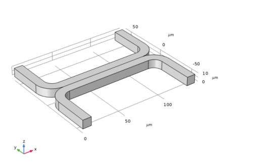
Extrude 1
Extrude the 2D geometry to create a 3D geometry.
1
Right-click Work Plane 1
and choose Extrude
.
2
In the Settings window for Extrude, locate the Distances section.
3
In the table, enter the following settings:
Distances (
μ
m
)
10
4
Click the Build Selected button
.
5
Click the Zoom Extents button
in the Graphics toolbar.