Roller Chain Geometry (3D)
In 3D, the part name for the roller chain geometry is roller_chain.
The sketch in Figure 2-29 shows all input parameters of the chain that can be used to customize the geometry part.
Figure 2-29: Sketch of the roller chain geometry in 3D and its cross-section.
Parameters Description
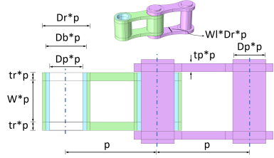
Table 2-9 shows the descriptions for all important input parameters of the roller_chain geometry part.
Optional Features
The following geometry operation is optional in this part:
Bushing between roller and pin plate. Set Db to zero to remove the bushings.
Selections
Table 2-10 describes the selections available for this part.