Roller Chain Sprocket Assembly Geometry (2D)
in 2D, the part name for roller chain sprocket assembly geometry is roller_chain_sprocket_assembly_2d.
The sketch in Figure 2-28 shows all input parameters of the roller chain sprocket assembly that can be used to customize the geometry part.
Figure 2-28: Sketch of the roller chain sprocket assembly geometry in 2D.
Parameters Description
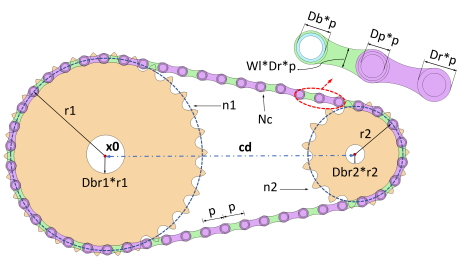
Table 2-7 shows the description of important input parameters for the assembly defined by roller_chain_sprocket_assembly_2d. For the input parameters related to the chain and the sprocket, see Table 2-3 and Table 2-5.
Part variants
There are two variants available for the roller_chain_sprocket_assembly_2d geometry part:
If you want to create a roller chain sprocket assembly by specifying the center distance between two sprockets, use the first variant of the part. In this case, the COMSOL software builds the geometry by calculating the minimum even number of links required to wrap the two sprockets placed at the given distance.
If you input instead want the provide the number of chain links, use the second variant of the part. For this variant, the COMSOL software adjusts the position of the second sprocket, such that the given number of links perfectly wraps around the two sprockets.
Note that in both these cases, the computation of the sprocket center distance and the number of chain links are based on nonlinear equations. Hence, there is a chance that the links may not tightly wrap around the sprockets. If you want to make minor adjustments in center distance between the sprockets, set the center distance correction parameter ccorr to one and tune the value of center distance correction factor cdelta accordingly.
Selections
Table 2-8 describes the selections available for this part.