Configuring and Exporting the Cosimulation File
You can continue with configuring the cosimulation and exporting the cosimulation file that will be loaded into Simulink. The most important cosimulation settings are:
You define the cosimulation settings in a Cosimulation for Simulink node that is added under Global Definitions in the Model Tree. You can add several Cosimulation for Simulink nodes to a model, for example to save different cosimulation settings for use with different Simulink diagrams.
1
2
Note: The name of the cosimulation file is independent of the model filename.
3
4
Note: Inputs can vary during simulation the cosimulation, hence parameters that affect the geometry or mesh are not allowed.
Note: Make sure that the units for the inputs are the same in the model and in Simulink as there is no unit conversion.
As there are no block parameters in this tutorial, continue with defining the outputs: the displacement at the tip of the actuator evaluated using the Domain Point Probe (comp1.ppb1) and the maximum temperature of the actuator evaluated using the maxop1 operator.
5
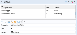
In the first row of the Outputs table, in the Expression column enter comp1.ppb1 , in the Unit column enter um, and in the Name column enter Disp.
6
In the second row, in the Expression column enter comp1.maxTemp and in the Name column enter Max temp.
Note: The text you enter in the Name column will be displayed for the corresponding output in the COMSOL Cosimulation block after the cosimulation file is loaded by the block. You may leave this column empty.
For time dependent study you need to specify the case of direct feedthrough, that is, when the output expressions are function of the inputs. This is important as direct feedthrough affects the execution order of the COMSOL Cosimulation block in Simulink or may induce algebraic loops. Direct feedthrough are defined under the Dependencies section by using the radio buttons.
In this model there is no direct dependencies between the input voltage and the actuator tip displacement or the maximum temperature, so you can go to the next section.
7
Note: The Study list contains only the allowed Study nodes for the cosimulation. If the list is empty, check that the model contains a study with a single stationary or time dependent study step, and that the study step does not include auxiliary sweep, load cases, or adaptation.
As the last step of setting up the cosimulation, choose the image that is displayed in the COMSOL Cosimulation block.
8
9
10
This image will be used as an icon in the COMSOL Cosimulation block. You can use any plot from the Graphics window or import your own icon. To import your own icon, browse to the desired file and then click Import.
11
After the export, the Filename text field displays the full file path for the cosimulation file.
12
In the following you will load the cosimulation file in Simulink and run the simulation.