Manual Mode for Remove Details
Automatic geometry cleanup is convenient as it saves time by automatically determining suitable tolerances and operations to remove geometric detail before meshing. Reviewing and modifying the Remove Details operation added for cleaning up this wheel rim geometry is possible by switching to manual mode.
1
Click the Remove Details 1
node in the Model Builder.
2
In the Settings window, locate the Mode of operation list and set it to Manual.
3
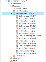
Expand the sequence to reveal the automatically generated sequence of virtual geometry operations.
In manual mode you can examine and edit each individual operation. You could, for example, exclude entities that you do not want to remove from the geometry. You could also add further virtual operations to the automatically generated sequence to remove additional entities.
Details are removed in different passes using increasing tolerances to remove larger and larger details. A simple geometry may only need one pass, but with a more complex geometry, like this wheel rim, the Remove Details operation goes through several passes and a cleanup pass at the end. Take a closer look at some of the virtual operations in the sequence.
4
In the Model Builder window, under Component 1 (comp1)>Geometry 1>Remove Details 1 (rmd1) click Collapse Faces 1 (aclf1)
.
5
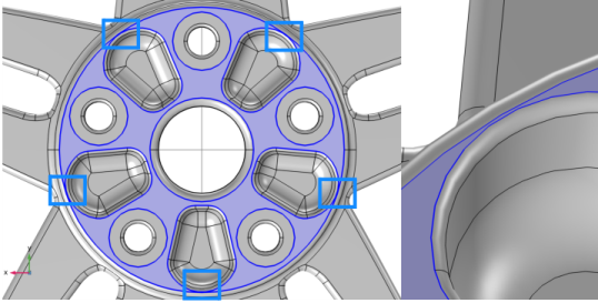
In the Settings window for Collapse Faces, under Faces to collapse, toggle the
Activate Selection toggle button.
6
Use the Zoom to Selection
button to find some of the faces on the rim.
Both small faces and sliver faces are removed in this operation. Small faces with sides that are similar in length are usually collapsed into a vertex, whereas sliver faces that have a high aspect ratio are more often collapsed into one of the longer edges. As an alternative to the Collapse Faces operation you can also use the
Merge Edges
operation that gives more control over which edges are kept when collapsing faces.
7
Click the Build Selected
button.
8
In the Model Builder window, click Ignore Edges 3 (aige3)
.
9
In the Settings window for Ignore Edges toggle the
Activate Selection toggle button, then find some of the edges on the geometry by using Zoom to Selection
.
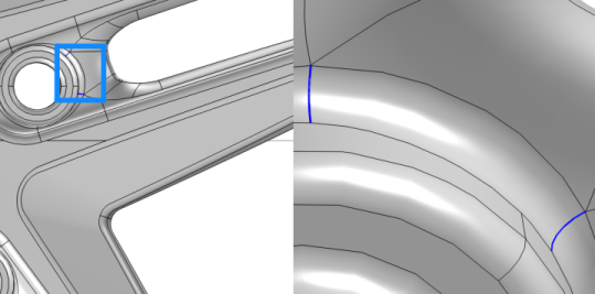
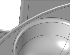
All edges in the list are next to sliver faces, similarly to the image displayed to the right. The sliver faces are wider compared to those that were collapsed in the previous operation. The faces on the two sides of the edge are continuous across the edge, and it is thereby suitable to form a larger composite face by ignoring the edge.
As an alternative to the Ignore Edges operation you can also use the
Form
Composite
Faces
operation.
10
Click the Build Selected
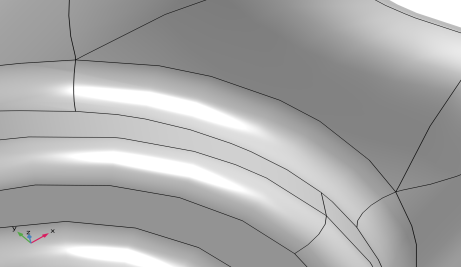
button. The geometry in the Graphics window is updated with the newly formed composite faces.
When removing edges, the adjacent vertices are deleted by downstream Ignore Vertices operations in the sequence. The sequence of virtual operations generated by Remove Details includes several Ignore Edges and Ignore Vertices operations to remove slivers with increasing face width.
In the following take a closer look at the
Collapse Face Regions
operation, that is added to the sequence to detect and remove narrow face regions.
11
In the Model Builder window, click Collapse Face Regions 1 (acfr1)
.
12
In the Settings window toggle the
Activate Selection toggle button.
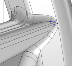
The face with the narrow regions is on the back of the rim.
13
Click Build Selected
in the Settings window for Collapse Face Regions.
The operation removes a detected narrow region by first partitioning the edges adjacent to it by creating vertices. Then, new edges are created between the vertices to partition the face. This creates a sliver face in place of the narrow region. As the last step, the created sliver face is collapsed into an edge.
Finally, switch Remove Details back to automatic mode, and mesh the geometry.
14
In the Model Builder window, click Remove Details 1 (rmd1)
.
15
In the Settings window for Remove Details, locate the Mode of operation list and set it to Automatic.
16
In the Mesh toolbar, click
Build All.