Viewing Selections
1
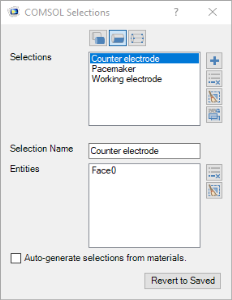
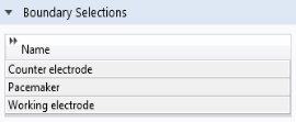
In the Settings window for LiveLink for Solid Edge, click to expand the Boundary Selections section.
2
The selections listed here are available for defining settings for the simulation, for example to define physics or mesh settings. Using selections can speed up the model setup as the entities only need to be selected once, when creating the selection in the Solid Edge file. The selections can then be used in multiple models that synchronize with the CAD file. Simulations containing parametric sweeps and optimization of geometric parameters can also become more robust as the LiveLink interface keeps track of the entities contained in a selection at the source, that is, in the CAD file.
You can view the selections defined on the pacemaker geometry in the Solid Edge file.
3
Switch to Solid Edge.
4
In the COMSOL Selection window that opens you can define selections that contain geometric entities, such as faces, edges, and points, solid and surface objects, and in the case of assembly files, components, such as parts and subassemblies. You can also create selections of features, that contain the geometric entities that result from the feature.