|
1
|
|
3
|
In the Radius text field, type r_outer.
|
|
3
|
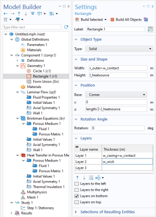
In the Width text field, type r_outer + w_contact.
|
|
4
|
In the Height text field, type l_heatsource.
|
|
5
|
Locate the Position section. In the z text field, type length/2-l_heatsource.
|
|
3
|
In the Width text field, type r_outer.
|
|
4
|
Locate the Position section. In the z text field, type length/2-l_heatsource*2.
|
|
2
|
Locate the Size and Shape section. In the Height text field, type length/2-l_heatsource*2
|
|
3
|
In the Settings window for Explicit Selection, type Vapor Cavity in the Label text field.
|
|
3
|
In the Settings window for Explicit Selection, type Porous Copper Wick in the Label text field.
|
|
3
|
In the Settings window for Explicit Selection, type Solid Copper Tube Casing in the Label text field.
|
|
2
|
In the Settings window for Explicit Selection, type Heat Sink in the Label text field.
|
|
5
|
In the Label text field, type Heat Source.
|
|
2
|
In the Settings window for Explicit Selection, type Cross Section of Cavity in the Label text field.
|
|
2
|
In the Settings window for Explicit Selection, type Cross Section of Wick in the Label text field.
|
|
2
|
In the Settings window for Explicit Selection, type Cross Section of Casing in the Label text field.
|
|
2
|
In the Settings window for Explicit Selection, type Inner Wick Boundary in the Label text field.
|
|
2
|
In the Settings window for Explicit Selection, type All Wick Boundaries in the Label text field.
|
|
2
|
In the Settings window for Union Selection, type All Cross Sections in the Label text field.
|