The Battery Layers domain node, available in 3D, allows for modeling of heat transfer in battery layers cells using a homogenized approach, where the individual layers of the cell do not need to be resolved in the computational mesh.
The effective In-layer (
kil) and
Through-layer thermal conductivities (
ktl),
Density and
Heat capacity values are specified by the user.
The Layer configuration setting specifies how to calculate the conductivity tensor and what coordinate system to use for defining the heat equation. If the layers are oriented in a
Flat parallel (pouch) configuration, the thermal conductivity tensor is defined using the default global Cartesian coordinates (
x,
y,
z). This would be the typical configuration for a pouch cell.
The Through-layer direction (plane normal) can be set to coincide with either the
x,
y, or
z coordinate axis, and the tensor is then defined in the (
x,
y,
z) system as either
For a Spirally wound (cylindrical) configuration, the thermal conductivity tensor is defined using the cylindrical coordinates (
rc,
ϕc,
zc) with the origin placed in the center of each battery cylinder and the
zc-axis pointing along the
Longitudinal axis of the cylinders, which is specified by the user to coincide with either the
x-,
y-, or
z-axis.
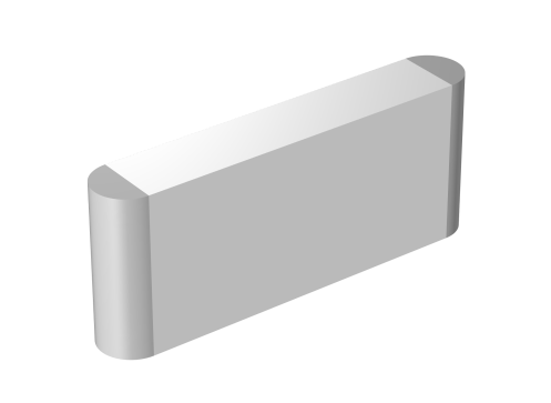
The Flat-sided oval (prismatic) configuration activates one
Semicylinder Selection child node and one
Rectangular Block Selection child node. The thermal conductivity tensor is defined in cylindrical coordinates for the
Semicylinder Selection and in Cartesian coordinates for the
Rectangular Block selection, as described above for the
Spirally wound (cylindrical) and
Flat parallel (pouch) configuration, respectively.
Multicylindrical coordinate systems, supporting multiple disjoint domains, are created automatically and selected when Spirally wound (cylindrical) is selected as
Layer configuration in the
Battery Layers section. For the
Flat-sided oval (prismatic) configuration, a multicylindrical coordinate system is selected for the
Semicylinder Selection child node.
 ,
,
 ,
,  ,
,  .
.