|
1
|
|
1
|
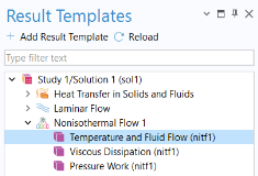
In the Temperature and Fluid Flow (nitf1)
|
|
2
|
|
1
|
|
2
|
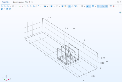
In the Settings window for 3D Plot Group, type Temperature of the channel walls and heat sink in the Label text field.
|
|
4
|
Select the Temperature and Fluid Flow (nitf1) node. In the Settings window for 3D Plot Group, locate the Color Legend section and clear the Show units checkbox.
 |
|
1
|
|
4
|
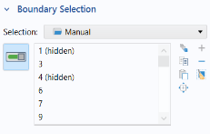
To add the channel walls, click the Paste Selection button
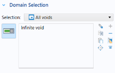
 By default the radiation direction is controlled by the opacity of the domains. The solid parts are automatically defined as opaque while the fluid parts are transparent. You can change this setting by using the Opacity feature in the Surface-to-surface Radiation interface. When the Diffuse Surface boundary condition defines the Emitted radiation direction as opacity controlled (the default setting), the selected boundaries should be located between an opaque and a transparent domain. The exterior is defined as transparent by default. Change the default setting to make the exterior opaque and have the radiation direction automatically defined on the channel walls. By default the radiation direction is controlled by the opacity of the domains. The solid parts are automatically defined as opaque while the fluid parts are transparent. You can change this setting by using the Opacity feature in the Surface-to-surface Radiation interface. When the Diffuse Surface boundary condition defines the Emitted radiation direction as opacity controlled (the default setting), the selected boundaries should be located between an opaque and a transparent domain. The exterior is defined as transparent by default. Change the default setting to make the exterior opaque and have the radiation direction automatically defined on the channel walls. |
 In the Graphics toolbar, click the Click and Hide button