|
1
|
|
3
|
|
4
|
|
5
|
|
4
|
|
5
|
|
3
|
|
4
|
|
4
|
|
5
|
|
3
|
|
3
|
|
4
|
|
4
|
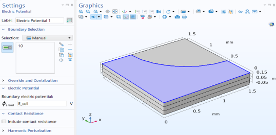
In the Settings window for Electric Potential, locate the Electric Potential section, and in the ϕs,bnd text field, type E_cell.
 |