Geometry 1
Now draw the model geometry. Use blocks to define the electrolyte and the porous electrode domains. Then use a workplane to draw the inlet hole at the top of the porous electrode. Facilitate geometry selection later (when setting up the physics interfaces) by enabling Resulting objects selection and renaming the geometry objects.
Begin by setting the default length unit to millimeters.
1
2
Create the First Block
1
2
3
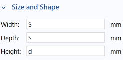
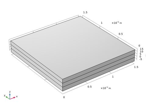
In the Settings window for Block, type Membrane in the Label text field.
4
-
-
-
5
6
Duplicate the Block and Change z Position
7
8
In the Label text field, type Cathode Gas Diffusion Electrode.
9
Duplicate the Cathode Block to Draw the Anode
1
2
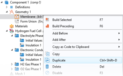
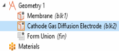
In the Settings window for Block, type Anode Gas Diffusion Electrode in the Label text field.
3
4
Create a Work Plane for Drawing the Inlet Hole
Proceed to draw the inlet hole, placed at the top of the cathode gas diffusion electrode block.
1
2
3
4
Draw the Inlet Hole
1
2
-
-
3
-
-
4
5
Form a Union to Finalize the Geometry
1
2