Fuel Cell and Electrolyzer Modeling
This module includes functionality to model fuel cell and electrolyzer unit cells that consist of:
Figure 1 shows a schematic drawing of a fuel cell unit cell and the structure of one of the GDEs. It represents a fuel cell unit cell and a magnified section of the cathode GDE and its contact with the electrolyte.
Figure 1: Fuel cell unit cell and a magnified section of the cathode GDE and its contact with the electrolyte.
Oxygen and hydrogen are supplied to the cell through the gas channels in the current collector and current feeder, respectively. The current collector and the current feeder are made of electrically conductive materials and are equipped with grooves that form the gas channels. These grooves are open channels with the open side facing the surface of the GDEs.
The current collectors and feeders also conduct the current to the wires connected to the load. They can also supply cooling required during operation and heating required during startup of the cell.
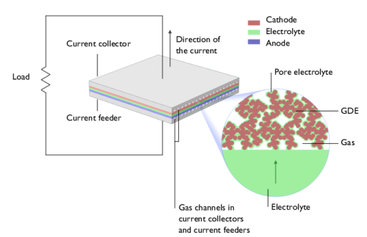
The GDE magnified in Figure 1 is an oxygen-reducing cathode in a fuel cell with an acidic polymer electrolyte (ionomer), for example, the proton exchange membrane fuel cell (PEMFC). In the PEMFC, the active GDE is confined to a thin active layer supported by a pure gas diffusion layer (GDL).
Figure 2: Transport of oxygen, water, protons, and electrons to and from the reaction site in an oxygen reducing GDE.
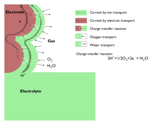
Figure 2 shows the principle of the oxygen reduction process in the electrode. From the bulk electrolyte, current enters the electrolyte contained in the GDE (also called pore electrolyte) as protons and is transferred to electron current in the charge transfer reaction at the reaction sites. These reaction sites are situated at the interface between the electrocatalyst in the electrode material and the pore electrolyte.
Figure 2 also describes the schematic path of the current in the electrode. The current in the pore electrolyte decreases as a function of the distance from the bulk electrolyte when it is transferred to electron current in the electrode. The direction of the current in the electrode is opposite to that of the electrons, by definition.
The supply of oxygen takes place in conjunction with the charge transfer reaction and can be subject to mass transport resistance both in the gas phase and in the thin layer of pore electrolyte that covers the reaction site.
The water balance in the electrode is maintained through evaporation and transport through the gas pores.
The pore electrolyte has to form a continuous path from the bulk electrolyte, between the anode and the cathode, to the reaction site. Also, the electrode material and the gas pores must each form a continuous path to the reaction site or to the pore electrolyte covering the reaction site.
The processes described above include fluid flow, chemical species transport, heat transfer, current conduction in the collectors, feeders, electrodes, and electrolytes, and the electrochemical reactions. These are all coupled together and determine the characteristics of a unit cell.
Several important design parameters, for varied operation conditions, can be investigated by modeling these processes. Among these parameters are: