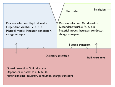
As show in Figure 3-1, a typical model consists of three domains. These domains represent the regions where charge transport and discharge phenomena occur, each characterized by specific material properties. Boundary features define the interactions at the edges of these domains, including insulating boundaries, electrodes, and interfaces between different media.
Electric discharges are primarily driven by the electric field E. In the Electric Discharge interface, the electric potential
V is introduced to solve for
E:
where V is a dependent variable that is solved across all domains. By default, the constitutive relation between the electric field
E and the displacement field
D is:
where ε0 (SI unit: F/m) is the permittivity of vacuum,
εr is the relative permittivity. Alternative dielectric models, such as those incorporating polarization effects, are also available.
For Insulator material model, Poisson’s equation is solved. The equation is the same for both stationary and time-dependent studies:
where ρ (SI unit: C/m
3) is the space charge density.
For Conductor material model, the current conservation equation is solved:
where Jc and
Jd represent the conduction and displacement current densities, respectively.
In general, the charge transport model solves for electrons (e), positive ions (
p), and negative ions (
n) in gas and liquid domains, while in solid domains, it solves for electrons (
e), holes (
h), and trapped electrons and holes (
te,
th).