|
1
|
|
1
|
|
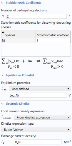
2
|
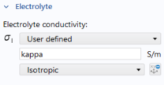
In the Settings window under Electrolyte, from the Electrolyte conductivity σl list, select User defined. Enter kappa in the text field.
|
|
5
|
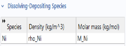
Click Add. In the table, type in Ni, rho_Ni, and M_Ni in the Species, Density, and Molar mass columns, respectively. Select Solve for surface concentration variables.
 |
|
-
|
|
8
|
|
9
|
|
3
|
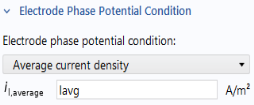
Under Electrode Phase Potential Condition select Average Current Density and type Iavg in the il, average text field.
 |
|
-
|