Secondary Current Distribution
Now, start setting up the current distribution model. Change the selection of the entire physics interface to the orange domain only.
1
2
Electrolyte I
The selection is locked to all selected domains of the physics interface, which in this case is the orange only.
1
2
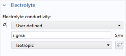
In the Settings window for Electrolyte, locate the Electrolyte section. Here the electrolyte conductivity can be set. From the σl list choose User defined and type sigma in the associated text field. sigma is defined in the Parameters node.
Electrode Surface I
Use Electrode Surface nodes to define both a metal electrode potential and an electrode electrolyte interface. Use a Butler–Volmer expression for the zinc electrode. The hydrogen kinetics are assumed to be very fast so that a linearized Butler–Volmer expression is applicable. Start with the Zinc nail (electrode).
1
2
3
Electrode Reaction I
1
2
3
4
5
6
7
8
9
10
In the αa text field, type alpha_a_Zn.
Electrode Surface 2
Define the copper nail (electrode) in a similar way with an Electrode Surface.
1
2
3
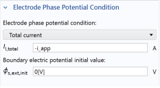
This cell is under galvanic control. Specify this in the Electrode Phase Potential Condition section by selecting Total current in the Boundary condition list and typing -i_app in the Il,total text field that appears. This parameter will also be used in the study to perform a galvanic polarization sweep over the cell.
Electrode Reaction 1
1
2
3
4
5
Initial Values I
We are using nonlinear kinetics in the model. Provide an initial value for the electrolyte potential in order to reduce solver time and improve convergence.
1
2
3
The interface node sequence in the Model Builder should now look like this: