Meshing the Geometry
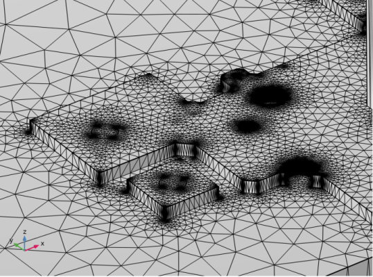
By using the Metal selection, as in the previous section, it is quite easy to generate a finer mesh only for the copper traces. Note that a mesh suitable for a simulation may be different from the one generated by following the steps below.
1
Click the Mesh 1 node, and in the corresponding Settings window change the Element size to Extra coarse and clear the checkbox Geometric Analysis, Details size in the Contributor table. Select User-controlled mesh from the Sequence type list box.
2
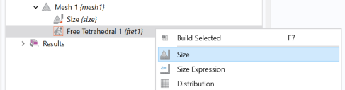
Right-click the Free Tetrahedral 1 node and select Size.
This adds a Size 1 node to the meshing sequence.
3
In the Settings window for Size 1 under Free Tetrahedral 1, change the Geometric entity level to Domain.
4
From the Selection list box select Metal.
As you can see the list contains selections corresponding to the layers resulting from the Import nodes. Since we do not need all these selections Import 2 node we can change the settings of Import 2.
5
Click the Import 2 node under Geometry 1.
6
In the Settings window for Import, select Off from the Show in physics list under Layer selections.
7
Switch back to the Size 1 node under Free Tetrahedral 1 in the Mesh 1 sequence.
8
In the Settings window for Size 1 the Selections list now only contains the selections from Import 1 in addition to the Manual and All domains options. Leave the Metal alternative selected.
9
From the Predefined list select Normal.
10
Finally, click the Build All
button to mesh the geometry.
11
Click the Mesh 1 node and zoom in the Graphics window.
 button to mesh the geometry.