Import
1
2
3
In your COMSOL installation directory navigate to the folder applications/ECAD_Import_Module/Tutorials and double click the file printed_circuit_board_si_geom.zip.
The Settings window for Import will now show the appropriate settings for the file, including the layers in the table under Layers section. As you can see from the table only the metal and dielectric layers are selected by default, the import of all other types of layers is turned off.
Note: For very large board layouts it is recommended to import one metal layer at a time to check the geometry of each layout in the PCB file. To avoid reimporting layers (this may take time for large layout files) when activating new layers in the table, you can add several import nodes to the geometry sequence, with each import node configured for a different layer.
4
The preview rendering consists of 2D representation of metal and drill layers, organized by layer and net, and colored according to the layer.
The Preview settings opened on the right side of the Graphics window consists of two sections. In the section Layers to Import, you can choose which layers to import and to display. In the section Nets to Import, you control which nets to import and to display. A specific part of the PCB will only be imported if both its layer and net are selected for import, with the analogous conditions applying for it to be displayed in the preview.
5
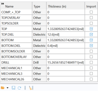
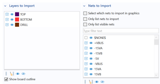
Select the checkbox for DRILL in the Layers to Import table in the Preview settings window.
6
When changing the values of checkboxes in these tables, it automatically updates the corresponding checkboxes in the table under Layer section and table under Nets to Import section in the Import settings window.
7
The imported geometry appears in the Graphics window.
The import can be configured to use one of 3 methods to generate 3D solid objects from the 2D layouts and group these together:
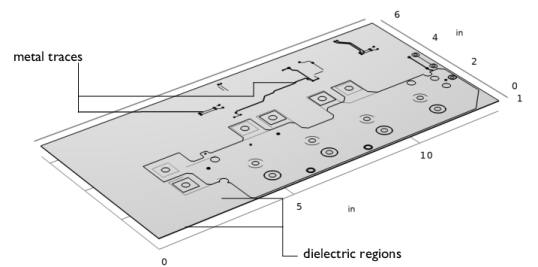
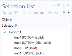
By default the Grouping of geometries property of the import node is set to By layer, which results in separate geometry objects for each imported layer. This is the most robust method for extruding the geometry from the 2D layouts, as each layer is extruded separately from the other layers.
When using the import method corresponding to Grouping of geometries set to All, a special extrusion method generates a single geometry object that includes domains, or regions, corresponding to the selected layers. While using this method may sometimes provide a faster route to meshing by avoiding the need to combine objects using the Form Union operation, it is more sensitive to inaccuracies between layers.
A third method, No grouping, generates separate objects for each symbol from the 2D layouts of the layers. This method can be useful for troubleshooting purposes, if the import of a layer fails with one of the other methods.
Note: Separate geometry objects are automatically combined into a composite object when the geometry is finalized by the Form Union operation, which appears at the end of the geometry sequence. An alternative that can lead to easier meshing for complex board geometries, and is suitable for most physics applications, is to switch the finalization method to Form Assembly. Read more about Form Union and Form Assembly in the COMSOL Multiphysics Reference Manual.
8
The top part of the Selection List window lists all geometry objects in the geometry sequence. The bottom part of the window lists all named selections, in this case the selections created for the layers by the import.
9
10