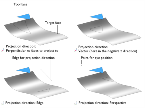
Use the Project to Faces (

) feature to create imprints on faces by projecting edges onto the face.
To add the feature to a geometry sequence, in the Geometry toolbar,
Booleans and Partitions menu, click
Project to Faces. You can also right-click the
Geometry node and add this node from the
Booleans and Partitions submenu.
Select the faces that you want to project to in the Graphics window. The faces appear in the
Faces to project to list. If the geometry sequence includes user-defined selections above the
Project to Faces node, choose
Manual to select faces, or choose one of the selection nodes from the list. Click the
Activate Selection button to toggle between turning ON

and OFF

the
Faces to project to selections.
Select the Imprint checkbox (default) to create imprints and partition the target faces. Clear this checkbox to keep the target faces unmodified, and to return the projected edges/vertices as separate objects with one output object for each object in the
Faces to project to selection. This checkbox is disabled and imprints are always created on the target faces if the Project to Faces feature is added after a Form Union/Form Assembly node in the geometry sequence.
From the Geometric entity level list, select
Edge (the default) to project selected edges, or select
Boundary to project the edges of selected faces. In both cases, choose the tool entities and add them to the
Entities to project list below.
Enter a value or expression to specify the Maximum distance (SI unit: m; default
Inf). Projected entities that are not entirely within this distance from the tool entities will be discarded from the result.
By changing the settings for the Repair tolerance list you can control the snapping of the projected entities to the existing edges and vertices on the target faces. Projected entities that are within a distance less than the repair tolerance from exiting edges or vertices on the target are snapped together.
Select the Extend projected edges checkbox (cleared by default) to make sure that all projected edges are connected to another edge at both ends.
Select the Resulting objects selection checkbox to create predefined selections (for all levels — objects, domains, boundaries, edges, and points — that are applicable) in subsequent nodes in the geometry sequence. To also make all or one of the types of resulting entities (domains, boundaries, edges, and points) that the resulting objects consist of available as selections in all applicable selection lists (in physics and materials settings, for example), choose an option from the
Show in physics list:
All levels,
Domain selection,
Boundary selection,
Edge selection, or
Point selection. The default is
Domain selection, which is suitable for use with materials and physics defined in domains. For use with a boundary condition, for example, choose
Boundary selection. These selections do not appear as separate selection nodes in the model tree. Select
Off to not make any selection available outside of the geometry sequence.
If you want to make the resulting entities contribute to a cumulative selection, select a cumulative selection from the Contribute to list (the default,
None, gives no contribution), or click the
New button to create a new cumulative selection (see
Cumulative Selections in the
COMSOL Multiphysics Reference Manual).
From the Construction geometry list choose
On to make the resulting objects available only in the feature’s geometry sequence. The default option
Inherit from input means that the resulting objects become construction geometry if all input objects are construction geometry. Choose
Off to never output construction geometry objects. For more information see
Construction Geometry in the
COMSOL Multiphysics Reference Manual.