To offset the faces of 3D geometry objects in the normal direction, from the Geometry toolbar,
Editing (

) menu, select
Offset Faces(

). You can also right-click the
Geometry node and add this node from the context menu.
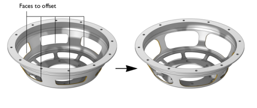
Select the faces that you want to offset in the Graphics window. They then appear in the
Faces to offset list. If the geometry sequence includes user-defined selections above the
Offset Faces node, choose
Manual to select faces, or choose one of the selection nodes from the list next to
Faces to offset.
Click the Activate Selection button to toggle between turning ON

and OFF

the
Faces to offset selections.
Select the Keep input objects checkbox if you want to use the selected geometry objects for further geometry operations.
When the Subtract input objects checkbox is selected, after the faces are offset, the corresponding input objects are subtracted from the offset objects.
Enter a Distance for the offset. Switching between a positive and negative number reverses the offset direction.
Select the Reverse side checkbox (cleared by default) to reverse the offset direction. This is equivalent to changing the sign of the offset distance.
Select the checkbox Fillet convex edges, cleared by default, to fillet convex edges between two offset faces. By default, such offset faces are instead extended until they meet.
The checkbox Perpendicular step edges for surface objects, cleared by default, applies to offsetting faces of a surface object, when the operation sometimes needs to split a vertex in two and introduce a step edge in between them. By default, the step edge is not perpendicular to an adjacent edge. With the checkbox selected, the created step edge is perpendicular to an adjacent edge.
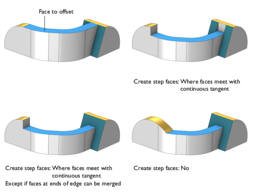
When Create step faces is set to
Where faces meet with continuous tangent you can select the checkbox
Except if faces at ends of edge can be merged (cleared by default) to extend and merge, if possible, the neighboring faces at the two ends of those bounding edges where faces meet with continuous tangent.
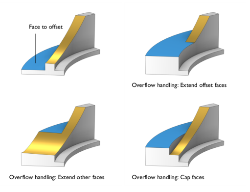
Use the Overflow handling setting to determine how to handle the case when an offset face moves beyond a nearby face in such a way that a wound (hole) appears. The following options are available:
If you want to make the resulting entities contribute to a cumulative selection, select a cumulative selection from the Contribute to list (the default,
None, gives no contribution), or click the
New button to create a new cumulative selection (see
Cumulative Selections in the
COMSOL Multiphysics Reference Manual).
Select the Resulting objects selection checkbox to create predefined selections (for all levels — objects, domains, boundaries, edges, and points — that are applicable) in subsequent nodes in the geometry sequence. To also make all or one of the types of resulting entities (domains, boundaries, edges, and points) that the resulting objects consist of available as selections in all applicable selection lists (in physics and materials settings, for example), choose an option from the
Show in physics list:
All levels,
Domain selection,
Boundary selection,
Edge selection, or
Point selection. The default is
Domain selection, which is suitable for use with materials and physics defined in domains. For use with a boundary condition, for example, choose
Boundary selection. These selections do not appear as separate selection nodes in the model tree. Select
Off to not make any selection available outside of the geometry sequence.
If you have Named Selections that include entities on the input objects, select the
Propagate selections to resulting objects (selected by default) checkbox to update the selections to corresponding entities on the output objects, when possible. Clear the checkbox to not propagate the selection to the resulting objects. Selecting this option can be useful in combination with selecting the
Keep input objects checkbox so that the selections refer only to the input objects.
From the Construction geometry list choose
On to make the resulting objects available only in the feature’s geometry sequence. The default option
Inherit from input means that the resulting objects become construction geometry if all input objects are construction geometry. Choose
Off to never output construction geometry objects. For more information see
Construction Geometry in the
COMSOL Multiphysics Reference Manual.