The Loft Operation
1
Right-click the Loft 1 node
, then select Build Preceding
.
2
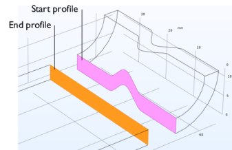
In the Settings window for Loft, expand the Start Profile and End Profile sections.
The loft operation generates a solid object to connect the rectangular cross-section of the bracket with the cross-section of the elbow.
3
To get a better view of the start and end profiles click the Wireframe Rendering
button in the Graphics toolbar ad use the mouse to zoom in.
The faces selected as the start and end profiles are highlighted in the image below.
While in this case the input consists of a start and an end profile, it is possible to define additional profiles in the Profiles section.
4
In the Loft toolbar click the Build Selected
button.
Loft Direction
1
Click the Wireframe Rendering
button in the Graphics toolbar.
2
In the Graphics window move and rotate the object to get a view perpendicular to the zx-plane. Then zoom in to get a view similar to that in the figure.
In case on your screen the lofted object does not appear to match the start profile you can adjust the visualization settings for the Graphics window.
3
From the File menu select Preferences; then on the Graphics page set Detail to Fine; confirm with clicking OK.
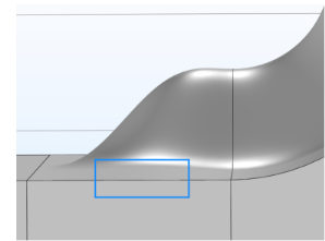
The default setting for the start and end profiles does not prescribe a loft direction. As a result of this the tangent of the lofted surface does not match the tangent of the adjacent surfaces.
In the following steps you will test the available loft direction options to create a surface with continuous tangent across the profile.
4
In the Start Profile section, from the Loft direction list select Parallel.
5
In the End Profile section, from the Loft direction list select Parallel.
6
For both the Start Profile and End Profile sections make sure that the Relative to list is set to Adjacent faces.
7
Click Build Selected
.
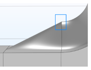
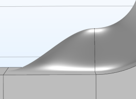
With the loft direction parallel to the adjacent faces the tangent of the lofted surface matches that of the adjacent surfaces along the edges of the start and end profiles. While this results in a better surface close to the profiles it may be good to examine the surface in other places. In this case the edge highlighted in the figure is no longer straight.
8
In the Start Profile section, from the Loft direction list select Perpendicular.
9
From the Relative to list select Profile faces.
10
In the End Profile section, from the Loft direction list select Perpendicular.
11
From the Relative to list select Profile faces.
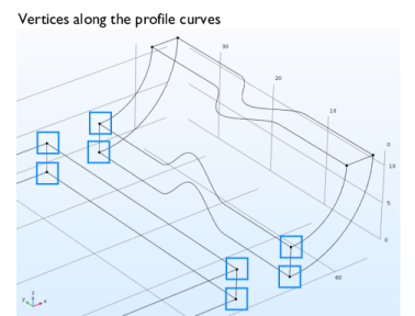
The perpendicular to profile faces loft direction ensures that the tangent of the lofted surfaces matches the normal vector of the profile faces at vertices along the profile curve. In this case there are four vertices, one at each corner of the start and end profiles.
12
Click Build Selected
.
The overall result is better compared to the Parallel loft direction, since the constraint on the tangent influences the entire surface, even though it is applied only at the vertices.
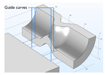
Guide Curves
To get an even better result create guide curves to be used with the loft operation. The guide curves connect the profile curves, thus prescribing a shape that the lofted surface will follow. Each guide curve must have a continuous tangent, and intersect each profile curve exactly once. Note that the guide curves cannot be used with the loft direction set to parallel to adjacent faces. Both the Perpendicular and Not prescribed loft directions support the use of guide curves.
1
In the Model Builder right-click the Loft 1 node, then select Build Preceding
.
The above step is important as it makes the Block 1 node the current node, which is symbolized by a green square around the icon for the node. The geometry operations that you add to the sequence are going to be inserted after the current node.
2
In the Geometry toolbar click More Primitives
, then choose Polygon
.
3
In the Settings window for Polygon, from the Data source list select Table.
4
In the table enter the following coordinates:
x (mm)
y (mm)
Z (mm)
lX-rOut-2*thk
lY/6-1
thk
lX-rOut
lY/6-1
thk
You can copy and paste the expressions from the table above.
5
Click Build Selected
.
6
To create the second curve right-click Polygon 1 and from the menu select Duplicate.
7
Use the following coordinates for Polygon 2:
x (mm)
y (mm)
Z (mm)
lX-rOut-2*thk
lY/3+1
thk
lX-rOut
lY/3+1
thk
Since the curve is a copy of the previous one you need only edit the y coordinates.
8
Click Build Selected
.
9
Right-click Polygon 2 and from the menu select Duplicate.
10
In the Coordinates table for Polygon 3 enter:
x (mm)
y (mm)
Z (mm)
lX-rOut-2*thk
lY/3+1
0
lX-rOut
lY/3+1
0
11
Click Build Selected
.
12
Finally, to create the last curve right-click Polygon 1 and from the menu select Duplicate.
13
In the Coordinates table for Polygon 4 enter:
x (mm)
y (mm)
Z (mm)
lX-rOut-2*thk
lY/6-1
0
lX-rOut
lY/6-1
0
14
Click Build Selected
.
15
In the Model Builder click the Loft 1 node, then in the Settings window for Loft expand the Guide Curves section.
16
Under Guide objects click the Active button.
17
From the Graphics window select the four guide curves:
pol1, pol2, pol3, pol4
.
18
Click Build Selected
.
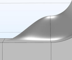
Using a loft direction perpendicular to profile faces together with guide curves results in lofted surfaces that have desired continuity for the surface tangent.