Adding Constraints to the Sketch
1
This activates the smart constraint mode where you can constrain geometric entities by selecting them in the Graphics window. Depending on the geometry and selected entities, a constraint is automatically suggested by the software. You may choose to apply the suggested constraint or change it to a different constraint.
2
The perpendicular constraint is suggested, and its symbol appears under the pointer.
3
Note that in the Model Builder, the Perpendicular 1 node has been added under the geometry sequence. Similar to all other geometry features, you can select the node to change its settings.
4
5
6
7
The geometry should now look similar to the one displayed below.
You have now applied the constraints needed to define the relations between the entities in the drawing.
8
9
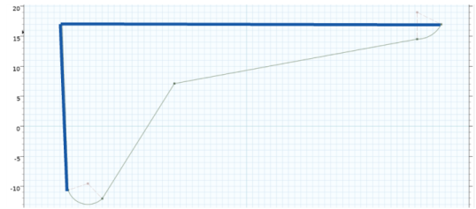
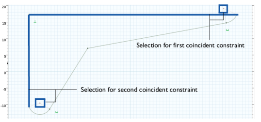
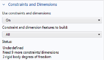
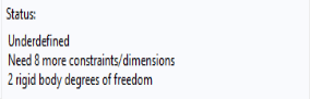
The goal when applying constraints and dimensions is to obtain a fully constrained sketch that is not possible to modify by dragging in the Graphics window. Such a geometry is called well defined. The bracket geometry is currently still underdefined. It is not recommended to leave a sketch in an underdefined state as several solutions exists, and modifying a dimension, for example by a parametric sweep, may lead to unpredictable results.
10
11
As you can see from the information in the Settings window the geometry is underdefined, and it needs 9 more constraints or dimensions. The rigid body translational and rotational degrees of freedom are not yet locked, meaning that the entire sketch can be moved around freely as a rigid body. To lock the rotational degree of freedom you can for example apply the Vertical or Horizontal constraints to an edge.
12
13
Only 8 more constraints or dimensions need to be applied until the geometry becomes well defined.