Use an Explicit node (

) to create the selection using the selection tools for individual geometric entities (boundaries, for example) on the chosen geometric entity level. To add this node, right-click the
Definitions node and choose
Selections >
Explicit.
Based on space dimension, select a Geometric entity level:
Domain,
Boundary,
Edge, or
Point for the geometric entities to add or remove from the selection list.
Select and add geometric entities in the Graphics window, using other selection methods, or by selecting the
All domains,
All boundaries,
All edges, or
All points checkbox. The selected items are highlighted in the
Graphics window. Selecting the checkbox for all geometric entities locks all entities of this type as selected even if the geometry changes.
If Boundary (for 2D and 3D models) or
Edge is selected, also select the
Group by continuous tangent checkbox to extend the selection to all adjacent faces or edges that have continuous tangents (an angle less than the value in the
Angular tolerance field) at their junctions. This grouping makes it possible to select all faces that make up a continuous sheet, for example. When the
Group by continuous tangent checkbox is selected, set the tolerance on the continuity condition in the
Angular tolerance field as the maximum angle between two faces or edges that are considered as having continuous tangents (a value between 0 and 180 degrees; the default value is 5 degrees).
If Domain is the input the default output is the
Selected domains. Select
Adjacent boundaries,
Adjacent edges, or
Adjacent points to use the boundaries, edges, or points next to the selected domains as the selection output (available options depend on the space dimension of the Component). If the output entities have a lower dimension than the input entities, there are also options to select exterior and interior entities of the union of the input selections. This makes it possible to, for example, make a selection of all boundaries around a domain by first selecting the domain.
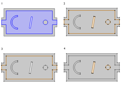
Select the Interior boundaries checkbox to include the interior boundaries in the selection, as shown in
Figure 6-23.