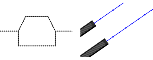
Edge
Use Edge () to mesh edges in 1D, 2D, and 3D. This is useful not only for intervals in 1D, but also for applications where the physics is solved on edges in 2D and 3D, as seen in Figure 8-54.
Figure 8-54: The image to the left shows the mesh for a pipe flow computation on edges in 2D. The image to the right shows the edge mesh for beams (highlighted in blue) connected to solids.
You can control the number of elements and the distribution of elements in the edge mesh by using Size and Distribution nodes.
To add an Edge node, select edges in the Graphics window, then choose one of the following:
Right-click in the Graphics window and select Edge () from The Graphics Context Menu.
In The Mesh Toolbar, choose Edge from the More Generators menu () (3D and 2D components) or click Edge () (1D components).
Right-click the Mesh node and choose Edge () (under More Generators in 3D).
Then enter the properties using the following sections:
Entity Selection
To define the edges where you want a create a mesh, first choose the level of the geometric entities from the Geometric entity level list:
Choose Entire geometry to specify an edge mesh for the entire geometry.
Choose Remaining to specify an edge mesh for remaining, unmeshed edges.
Choose Edge (3D), Boundary (2D), or Domain (1D) to specify the edges for which you want to create a mesh. Choose Manual in the Selection list to select the edges in the Graphics window, choose a named selection to refer to a previously defined selection, or choose All edges (3D), All boundaries (2D), or All domains (1D) to select all edges.
Control Entities
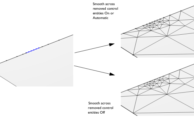
Use the Smooth across removed control entities setting to smooth the transition in element size across removed control entities. Use Automatic (default) to let the algorithm decide if to apply smoothing or not. Smoothing will be applied if, for example, 2D domains adjacent to edges with a removed vertex contain triangular elements only. When set to On, the mesher adjusts the sizes of the mesh elements to get a smoother transition from large to small elements by adjusting the locations of the mesh vertices on the entity that is removed. Select Off to not adjust the mesh. When set to On, you can specify the number of smoothing iterations in the Number of iterations field. In the Maximum element depth to process field you can specify the maximum element depth for the mesh vertices to be smoothed.
Figure 8-55: Comparing the edge meshes for different Smooth across removed control entities settings. The vertices adjacent to the highlighted edge (blue in left image) are designated as Mesh Control Vertices. When the face adjacent to the edges has been meshed, the vertices are removed, leaving only one single edge. With the Smooth across removed control entities set to On, the sizes of the edge elements are adjusted (upper-right image). With the setting set to Off, the edge mesh is not adjusted (lower-right image). As the adjacent face is meshed with a triangle mesh, the Automatic option gives the same result as On.
For a 3D tutorial, see Connecting Beams and Solids:
Application Library path Structural_Mechanics_Module/Beams_and_Shells/beam_solid_connection.
For a 3D tutorial, see Magnetic Field of a Helmholtz Coil:
Application Library path ACDC_Module/Devices,_Inductive/helmholtz_coil.
For a 2D tutorial, see Slurry Transport:
Application Library path Pipe_Flow_Module/Tutorials/slurry_transport.
For a 1D tutorial, see Lithium-Sulfur Battery:
Application Library path Battery_Design_Module/Batteries,_General/lithium_sulfur.