Use a Union (

) operation to create the union of selected geometry objects, as shown in
Figure 7-98.
To add a Union operation, in the
Geometry toolbar, from the
Boolean and Partitions (

) menu, select
Union (

). You can also right-click the
Geometry node to add this node from the
Boolean and Partitions submenu. Then enter the properties of the union operation.
From the Input objects list, choose
Manual (default) to select the geometry objects that you want to unite in the
Graphics window. Click the
Activate Selection button to toggle between turning ON

and OFF

the
Input objects selections. Alternatively, choose
All objects to select all objects or choose
All nonconstruction objects to automatically select all objects that have not been marked as
Construction Geometry. If the geometry sequence includes user-defined selections above the
Union node, you can choose one of the selections from the
Input objects list.
Select the Keep input objects checkbox to use the selected geometry objects for further geometry operations.
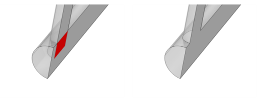
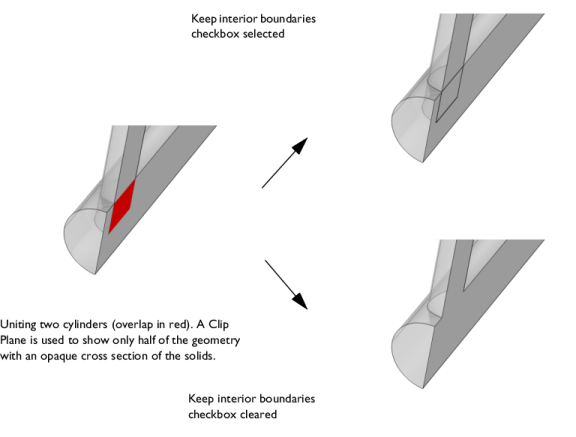
Create a geometry object without interior boundaries by clearing the Keep interior boundaries checkbox, as shown in
Figure 7-99. This can be useful to simplify a geometry where the interior boundaries do not separate domains with different physics nodes or materials, for example.
You can change the settings for the Repair tolerance list if you experience problems with the union operation. Geometric entities that have a distance less than the repair tolerance are merged.
Select the Resulting objects selection checkbox to create predefined selections (for all levels — objects, domains, boundaries, edges, and points — that are applicable) in subsequent nodes in the geometry sequence. To also make all or one of the types of resulting entities (domains, boundaries, edges, and points) that the resulting objects consist of available as selections in all applicable selection lists (in physics and materials settings, for example), choose an option from the
Show in physics (
Show in instances if in a geometry part;
Show in 3D in a plane geometry under a work plane in a 3D component) list:
All levels,
Domain selection,
Boundary selection,
Edge selection, or
Point selection. The default is
Domain selection, which is suitable for use with materials and physics defined in domains. For use with a boundary condition, for example, choose
Boundary selection. These selections do not appear as separate selection nodes in the model tree. Select
Off to not make any selection available outside of the geometry sequence. From the
Color list, choose a color for highlighting the resulting objects selection. See
Selection Colors.
If you have Named Selections that include entities on the input objects, select the
Propagate selections to resulting objects (selected by default) checkbox to update the selections to corresponding entities on the output objects, when possible. Clear the checkbox to not propagate the selection to the resulting objects. This can be useful in combination with selecting the
Keep input objects checkbox so that the selections refer only to the input objects.
From the Construction geometry list choose
On to make the resulting objects available only in the feature’s geometry sequence. The default option
Inherit means that the resulting objects become construction geometry if all input objects are construction geometry. Choose
Off to never output construction geometry objects. For more information, see
Construction Geometry.