To delete geometry objects or geometric entities from objects, right-click a geometry and select Delete Entities (

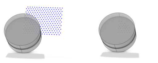
), as shown in
Figure 7-67. Then enter the properties of the delete operation in the
Input section. If you delete objects corresponding to primitive features these nodes disappear from the sequence. If you delete other objects or if you delete geometric entities, a Delete Entities node appears in the sequence.
From the Geometric entity level list, choose the level of the entities to delete:
Object,
Domain, or
Boundary (that is, faces in 3D and edges in 2D),
Edge (3D only), or
Point. From the
Selection list, choose
Manual (default) to select the geometry objects that you want to delete in the
Graphics window. Click the
Activate Selection button to toggle between turning ON

and OFF

the
Input objects selections. Alternatively, choose
All objects to select all objects or choose
All nonconstruction objects to automatically select all objects that have not been marked as
Construction Geometry.
For the other levels, select the entities that you want to delete in the Graphics window or use the
Selection List window. Click the
Activate Selection button to toggle between turning ON

and OFF

the
Input objects selections. The entities appear in the
Selection list when you have confirmed (locked) the selection in the
Graphics window. If the geometry sequence includes user-defined selections above the
Delete Entities node, choose
Manual to select entities, or choose one of the selection from the
Selection list.
Select the Resulting objects selection checkbox to create predefined selections (for all levels — objects, domains, boundaries, edges, and points — that are applicable) in subsequent nodes in the geometry sequence. To also make all or one of the types of resulting entities (domains, boundaries, edges, and points) that the resulting objects consist of available as selections in all applicable selection lists (in physics and materials settings, for example), choose an option from the
Show in physics (
Show in instances if in a geometry part;
Show in 3D in a plane geometry under a work plane in a 3D component) list:
All levels,
Domain selection,
Boundary selection,
Edge selection, or
Point selection. The default is
Domain selection, which is suitable for use with materials and physics defined in domains. For use with a boundary condition, for example, choose
Boundary selection. These selections do not appear as separate selection nodes in the model tree. Select
Off to not make any selection available outside of the geometry sequence. From the
Color list, choose a color for highlighting the resulting objects selection. See
Selection Colors.
From the Construction geometry list choose
On to make the resulting objects available only in the feature’s geometry sequence. The default option
Inherit means that the resulting objects become construction geometry if all input objects are construction geometry. Choose
Off to never output construction geometry objects. For more information, see
Construction Geometry.