Use a Rectangle (

) or
Rectangle (Center) (

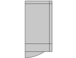
) node to add a rectangle or bounding box to your geometry, as shown in
Figure 7-48.
To add a Rectangle node, choose one of the following:
When you have added a node or finished drawing the rectangle in the Graphics window, you can use the following section to define it or fine-tune it.
From the Type list, select
Solid (default) or
Curve to specify if the rectangle is a solid object or a curve object.
From the Defined by list, select
Size and position (default) to specify the width and height for the rectangle as well as specify its position. Select
Bounding box (approximate) to create a rectangle that approximately bounds a selection of objects or entities. A bounding box is useful to replace a complicated imported object with a rectangle or to create a fluid domain around objects.
From the Orientation list, select
Principal axes (default) to let the orientation of the bounding box be determined by the principal axes of the input entities. Select
Manual to manually specify the orientation in the
Rotation Angle section.
From the Base list, choose
Corner (default) if a surrounding box has a corner at the position, or choose
Center if the rectangle is centered about the position. For
Position type set to
Coordinates (default), enter the position using the
x and
y fields. For
Vertex, select a point in the
Graphics window. Click the
Activate Selection button to toggle between turning ON

and OFF

the
Position selections.
This section is shown if Defined by is set to
Bounding box (approximate). From the
Geometric entity level list, choose the level of the entities to bound:
Object (default),
Domain, or
Boundary, or
Point. From the
Selection list, choose
Manual (default) to select the geometry objects that you want to bound in the
Graphics window. Click the
Activate Selection button to toggle between turning ON

and OFF

the
Input objects selections. If the geometry sequence includes user-defined selections above the
Rectangle node, you can choose one of them from the
Selection list. Alternatively, choose
All objects to select all objects or choose
All nonconstruction objects to automatically select all objects that have not been marked as
Construction Geometry.
For the setting Geometric entity level: Object, select the checkbox
Keep input objects (selected by default) to keep the objects that are bounded. Clear the checkbox to delete the selected objects.
This section is shown if Defined by is set to
Bounding box (approximate). Fill in the edit fields to enlarge the rectangle on the left, right, bottom and top (or shrink it if the values are negative).
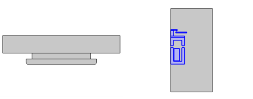
Layers can be used to create sandwich primitives by adding layers on one or more sides, as shown in Figure 7-49. This is especially useful when specifying artificial domains in the physics, such as Infinite Element Domains and Perfectly Matched Layers. You specify the thicknesses of layers in the
Layers table, and optionally a name for each layer. The outermost layer comes first. Select the checkboxes to specify where to apply the layers. Each layer must have a minimal thickness (depending on the size of the geometry).
Select the Create Parameters checkbox to automatically create parameters for the coordinates, size, and coordinate bounds of the rectangle to be used in further geometry creation, mesh size settings, or physics set up. The created parameters can be seen in the variable tree that appears when pressing Ctrl+Space in an edit field in another feature. If the 2D geometry is set up using constraints and dimensions, use
Measuring Dimensions and
Dimension Parameters instead.
Select the Resulting objects selection checkbox to create predefined selections (for all levels — objects, domains, boundaries, and points — that are applicable) in subsequent nodes in the geometry sequence. To also make all or one of the types of resulting entities (domains, boundaries, edges, and points) that the rectangle consists of available as selections in all applicable selection lists (in physics and materials settings, for example), choose an option from the
Show in physics (
Show in instances if in a geometry part;
Show in 3D in a plane geometry under a work plane in a 3D component) list:
All levels,
Domain selection,
Boundary selection, or
Point selection. The default is
Domain selection, which is suitable for use with materials and physics defined in domains. For use with a boundary condition, for example, choose
Boundary selection. These selections do not appear as separate selection nodes in the model tree. Select
Off to not make any selection available outside of the geometry sequence. From the
Color list, choose a color for highlighting the resulting objects selection. See
Selection Colors.
When the Layers table is nonempty, select the
Create layer selections checkbox to create predefined domain selections for each specified layer and for the core domain. To also make the domains available as selections in all applicable selection lists (in physics and materials settings, for example), select the
Show in physics (
Show in instances if in a geometry part or
Show in 3D if in a Plane Geometry) checkbox (ON by default).
Select the Construction geometry checkbox to make the resulting objects available only in the feature’s geometry sequence. For more information, see
Construction Geometry.